Power relay switch
08 August 2020Following on from my thermocouple circuit which came about from doing some reflow testing with a portable electric hot-plate, the next logical thing was to build a circuit to try out power relay switches, and this latter circuit is the subject of this article.In the longer-term my idea is to create a circuit that allows the whole reflow to be automated, although I suspect that modding the hot-plate for such a thing is a project for the distant future.
Circuit design
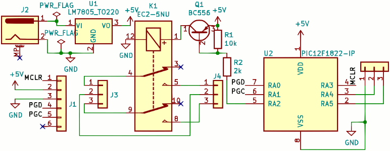
Had I got my USB-controlled I2C master at hand I probably would have used an I/O Expander such as thePCF8574 but since I did not I instead had to rely on RS232 as the external interface, and the schematic for such a circuit is shown below. Like all of my PCBs these days it was designed using KiCad and it only makes use of symbols included in the standard library.
I have made revision 2 of the PCB available under the CERN Open Hardware Licence which is pretty much a hardware version of the GPL.
The only difference between the second revision of the PCB and the first revision covered here is some changes to the silk-screen text.
Relay switch
The power switch itself is a KemetEC2-5NU mechanical signal relay, which is intended to allow a 5-volt control signal to switch 2 amperes at 250 volts.
It has two poles so it switches both the active and neutral wires at the same time, and it is the unlatched type so it switches off if there is no coil voltage, rather than needing a reversed voltage.
I suspected that the current needed to activate the switch coil might be more than what the microcontroller is specified for, so the relay is controlled indirectly via a transistor.
Microcontroller
For this circuit I used thePIC12F1822 which is basically identical to the PIC12F1840 I had recently used for another project, and both of these are from the family of PIC microcontrollers I long ago decided to standardise on as much as possible.
It provides the external RS232 interface which was simply the most expedient thing to use for the control commands, although making it bi-directional rather than just having the receive line was force of habit rather than for any specific use-case
In-circuit programming
I have a preference for in-circuit programming via a dedicated header because it makes so many problems go away. Swapping chips in and out like I did with my previous circuit carries the risk of trashing the chip's legs, so the care required adds to what is already a tedious process. Using a programming clip for a SSOP chip is not quite as bad, but in the past I have had headaches with clips not getting a good grip. For this circuit I opted for the easy life.Power supply
Since this circuit was more or less intended to switch on and off an AC power supply I had thought about powering the circuit from the AC power, but the circuitry needed to convert 240-volt AC into the 5-volt DC would actually be a project in itself more complex than the primary use of this circuit. By the time I factored in the price of a transformer and the PCB real-estate it would need I would be better off buying in off-the-shelf solutions.PCB layout and fabrication
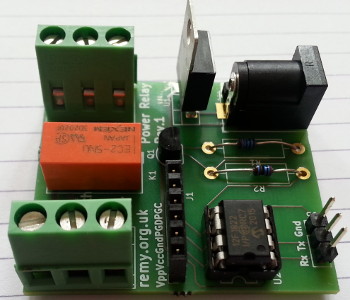
Apart from some bodge boards that contained no actual components this is the first PCB since my auxiliary power supply for PIC programming that has only through-hole components. Even the PIC16F88 Timer PCB which was my first proper PCB had a few surface-mounted components for reasons of space, and before long I found that for some components I actually found surface-mounted variants easier to work with even when hand-soldering. It is only things with fine-pitched pins such as TSSOP and QFP that I have any dislike for. For this circuit I avoided using any SMD components because I did not consider the expense of a solder mask justifiable and I felt that the resources I had to hand were unsuitable for trying to hand-solder them.Track widths
The tracks for the AC power are intentionally a lot wider than normal to account for the higher voltages, and according to the KiCad calculator the 1.5mm is ample for 2 amps at 240 volts that the relay itself can switch. The circa 500 watts this corresponds to is underpowered for anything heating-related but it should be ample for most other things. Concern over current carrying capacity was a major reason why I did not attempt to build this circuit using perf-board even though all the components used were through-hole.Aisler vs. Seeedstudio
As with many PCBs I have ordered in the last few weeks I used Aisler for the fabrication. They now provide two services — one that uses HASL that has a two-day turnaround, and another that uses ENIG that takes five days. There does not appear to be any difference in cost, but the milling needed for the barrel jack holes was not supported on their faster HASL offering. Shipping was a further two working days. In the past I have batched up several PCBs in order to amortise Seeedstudio's shipping costs, but in practice this resulted in a significant number of PCBs that never made it as far as becoming successful projects. Some were boards with dubious use-cases to start with; some were for projects such as my bidirectional radio that due to a combination of delays and circumstances were effectively abandoned; and some such as my re-purposed LED Control that were outright botched.Aisler pricing
About a month or two ago Aisler changed their pricing model from a graded price-per-cm2 to one that is a flat €10.20, plus 8.4¢ per cm2 per board, plus VAT at 16%. They did release a Ruby file to calculate this but I gave up trying to get it working and ended up having to RTFS to get the values. The reported reason for the change was to reduce the cost of large orders although my suspicions there are other undeclared reasons. As it happens I was able to compare the price I paid for some previous PCBs with the price I would be charged today and these are summarised in the table below.
| Circuit | Size (cm2) | Order date | Old price | New price |
| LCD Timer | 55.57 | 19 July 2020 | n/a | €28.08 |
| ARM MicroMaTch | 6.31 | 18 March 2020 | 10.10 | 13.68 |
| LPC11U24 USB | 17.39 | 15 Feburary 2020 | 16.67 | 16.92 |
| KE04 I2C master | 6.96 | 6 November 2019 | 10.53 | 13.86 |
| ARM programming adapter | 12.96 | 14 March 2019 | 11.25 | 15.51 |
| USB-I2C adapter | 9.17 | 22 October 2018 | 8.55 | 14.52 |
| 17 segment LED module | 4.70 | 30 June 2018 | 5.70 | 13.23 |
| Column driver board | 23.31 | 26 August 2017 | 18.00 | 18.57 |
| Power mini-PCB | ~3.5 | 29 July 2017 | 3.87 | 12.81 |
| LED display (part 2) | 46.8 | 9 July 2017 | 30.88 | 25.44 |
| PCB | Description | Manufacturer | Part number |
U2 |
Microcontroller | Microchip | PIC12F1822-I/P |
U1 |
5v linear regulator | ON Semiconductor | MC7805ACTG |
Q1 |
PNP transistor | BC556BTF |
|
K1 |
Relay switch | Kemet | EC2-5NU |
R1 |
10kΩ resistor | Multicomp | MF12 10K |
R2 |
2kΩ resistor | MF12 2K |
|
J1 |
Programming receptacle | 2212S-06SG-85 |
|
J2 |
Barrel jack | Cliff Electronics | FC681465P |
J3,J4 |
Terminal block | Phoenix Contact | MKDS 1,5/3 |
J5 |
Pin header strip | Harwin | M20-9991045 |
Firmware
Since the circuit as a whole is only intended as a proof-of-concept, the firmware is pretty simplistic in the interface it provides and there is not much to really say about it here. The firmware it switches the relay on if a1 is received over the RS232 connection, off if a 0 is received, and any other character has no effect.
I did consider adding some extra functionality such as timed pulses or periodic switching, but without an immediate use-case for such things to be off-loaded to the microcontroller, I decided against implementing such things.
Clock speed
Since the firmware does not do much I had intended to clock the chip as low as possible, and the limiting factor is the 9600 BAUD I decided to use for the serial connection. At a clock speed of 500kHz and a 16-bit Baud Rate Generator divisor value of0x000c the actual BAUD rate is 9615, which is well within the tolerances required for nominal 9600 BAUD.
However with the divisor value already close to zero, there is not a suitable value for 9600 BAUD at lower clock speeds.