ARM programming connections
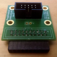
27 March 2019My article on NXP LPC1112 I/O utilised, but did not detail, a breakout adapter for ARM programming/debugging connections. In previous test circuits it worked fine, but with my latest ARM-based circuit I ran into trouble with OpenOCD not making a connection to the micro-controller. The problem was eventually traced down to the wires being too long for the programmer/debugger connections, which in itself justified an article, but then I realised that I had not documented anywhere the wiring for the mini-PCB. I ended up making a second revision of this adapter, which is shown below.
10-pin flashing connections
Unlike previous ARM-based circuits I used a 10-pin IDC connector for the programming interface, and due to to the number of pins actually required for programming/debugging this is the connector I planned to standardise on — the connector on the OlimexARM-JTAG-20-10 (Farnell 2144328) was simply too small for all my requirements. In order to connect the board I was building at the time I was using an adapter — described later — that joins together the 20-pin cable from the debugger to the 10-pin cable connected to the board, and this setup is shown below.
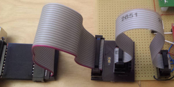
I later found out that using two IDC ribbon cables in this fashion would not work due to limits on the JTAG electrical path length, which was solved by making modifications to the breakout adapter.
Flash adapter pinning
The 20-pin and 10-pin IDC connectors are MulticompMC-254-20-00-ST-DIP and MC-254-10-00-ST-DIP respectively, and the pin wiring within the follows JTAG standards, or at least my interpretation of it. The pinning for the 20-pin connector is given in a previous article and for the 10-pin connector is summerised in the table below — note that this table shows the top-down view of the PCB receptacle and not the plug on the ribbon cable.
| JTAG name | Connector | JTAG name | |
| Vcc sense | 1 | 2 | TMS/SWDIO |
| Ground | 3 | 4 | TCLK/SWCLK |
| Ground | 5 | 6 | TDOSWO |
| unconnected | 7 | 8 | TDI |
| Ground | 9 | 10 | Reset |
The adapter also includes a 6-pin single-row connection, which is based on the six-pin programming connection used by the PICKit programming unit for Microchip PIC microcontrollers. I added it for situations where I needed a connection to either solderless breadboard or strip-board, as unlike perf-board these cannot take a two-row IDC connector. The pinning is shown in the table below, with all the different names for the pins I have come across.
| Pin | JTAG name | SWD name | Short name |
| 1 | Vcc sense | VCC | |
| 2 | TMS | SWDIO | SIO |
| 3 | TCLK | SWCLK | SLK |
| 4 | TDO | SWO | SWO |
| 5 | Reset | RST | |
| 6 | Ground | GND | |
Maximum lengths
When connecting to an ARM chip using OpenOCD there are limits to the length of the electrical connection between the debugger and the chip itself. I do not fully understand the electrical physics behind the limitation, and hence how to work around them, but documentation on JTAG suggests a limit of 20cm. To demonstrate the problem of wire lengths, and this is how it finally dawned on me after some shotgun-debugging, consider the circuit below. The circuit has an NXPLPC1112 ARM Cortex-M0 on the red breakout PCB — if wired as shown OpenOCD will not be able to connect to the Cortex-M0, giving output consistent with a disconnected or powered-down chip.
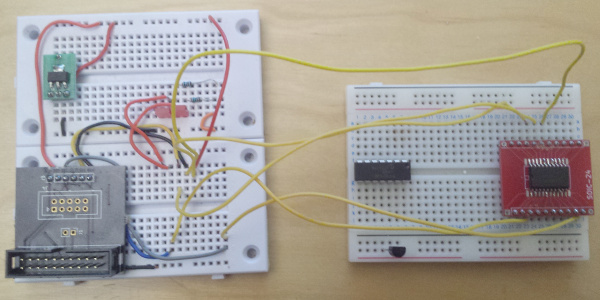
However if the Cortex-M0 is instead placed directly on the left-hand breadboard rather than connected via the yellow patch leads, a flashing/debugging session will successfully be establised. The IDC ribbon cables are 14cm each and the yellow patch leads are approximately 16cm long, so for the above circuit the electrical path is in the region of 30-35cm. With two ribbon cables — the setup of my original problem — the electrical path is at least 28cm.
Adapter modifications
Since the problem with connecting to the ARM chip was electrical path length, the solution was to eliminate the 20-pin ribbbon cable between the programmer/debugger and the breakout board, and connect them directly as shown below. This was done by soldering in a board-to-board receptacle that is mechanically identical to the IDC plugs on the ribbon cable, and is soldered onto the under-side of the PCB to take account of the mirroring of the pins within a plug versus the socket. The receptacle is a SamtecSSW-110-02-G-D-RA (Farnell 1668376), which at €2.67+VAT each is grossly over-priced for what it is.
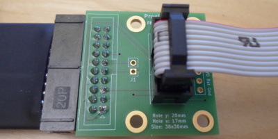
Due to the lack of a polarising notch, care has to be taken to make sure things are plugged in the correct way round. I used up the three adapters I had fabricated by OSH Park so I had some more fabricated and in the process made a second revision of the board: Some of the electrical traces were moved and bolt holes were added. The board had unused space, and I could foresee situations where I would want to secure this adapter with bolts.
Remarks
Much like when I made myself a supplementary power board when I started PIC microcontroller programming, this ARM programming adapter is in response to a problem that did not have an off-the-shelf solution. The programming adapter's design was essentially flawed due to not paying attention to total signal path lengths, but correcting the flaw ironically did not need any changes to the board itself — just substitution of a different component.Until I got the updated adapter back from fabrication I was not sure whether the circuit I was building would work properly, and due to the lead time being longer than expected I had to put the prior circuit project on hold for two months. Mistakes such as the one that caused this blockage are an inevitable side-effect of self-taught electronics, and no doubt I will make comparable ones in the future, but overall I have no regrets in creating my own infrastructure components such as this one.