LED matrix display
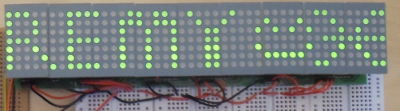
22 October 2017My first electronics project was an LED display where each dot was discretely wired, and long before I stopped working on it I knew it was not the way practical LED displays were wired up, but at the time I had different learning priorities with the project. In this project off-the-shelf LED matrices are used to create the 7-by-45 LED display shown below:
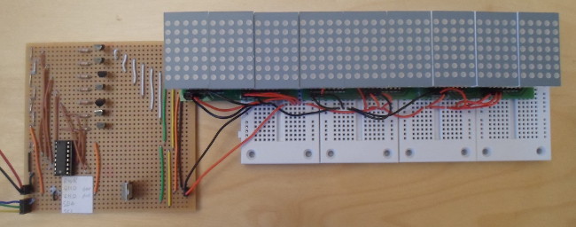
At the far left is the row driver board, from which the left-most of the three column driver board is attached. Connected to the top of each of the column driver boards is two LED matrix modules. All three are detailed later in the article. The two main pieces of experience in this project are the use of transistors and PCF8574 I/O expanders, which together will drive the 5x7 LED matrices.
Fritzing et al.
I am pretty certain it is not the best package out there, but the open-source Fritzing has become my go-to place when designing circuits, both when using stripboard and for making PCBs to be fabricated. It took a lot of time to really figure it out and it is laden with idiosyncrasies as well as some outright bugs, and the binary release is very out of date compared to the developmental version, but it gets the job done. To be fair in practice a lot of things that are annoying in Fritzing, such as awkward wire placements, are an outright headache on a physical circuit.The business model of the fabrication service I use is to only allow orders in multiples of three, so there is an inherent bias towards small reusable boards, rather than creating two spares of a one-off board that will in all probability will never be used. In the latter case the effective price including tax is around €0.91 per cm2, which for something like my programmer power board is sorta OK, but for anything more adventurous such as my first PCB this price is simply that bit too painful. As will be seen later, this is the root cause of what otherwise seems like odd design choices, most notably splitting up a circuit which ought to really be on a single board.
Design
As was mentioned in passing with my first LED display, with practical displays the LEDs are blinked at high speed rather than held on continually, in part because of the vast number of wires required for each LED to be powered individually. For this project, I used 7x5 LED matrices (Farnell 2112219) which I had previously used as the base for LED matrix modules. A single I/O expander — via transistors — will switch on and off the rows across all the LED matrix modules, and another expander will control which dots (i.e. columns) within a row are lit on each matrix. Below is a simplified schematic of this design:-
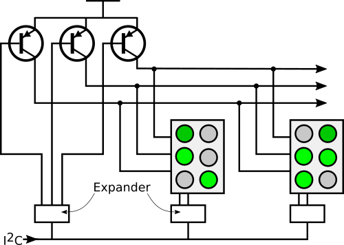
This design is driven by the PCF8574 I/O expanders having open drain outputs that act as grounding when “on”; for columns they provide grounding, and for the rows they activate the PNP transistors. Since LED displays are generally long rather than tall, it also made sense to activate a row at a time rather than a column, and as a result power rows across all LED modules from a single source. The LED matrix modules and the column driving I/O expanders will form a discrete unit, as this part can be tiled horizontally.
LED matrix modules
The basic idea with these LED matrix modules is that I wanted self-contained modules that I could easily plug into a circuit without much thought about how to wire it up correctly or having to worrying about what it was connected to. The off-the-shelf LED matrices I had previously obtained for some reason had pinouts with rows & columns mixed up in what seems to be random order, probably to allow it to be plugged in upside-down, which was something I did not really want to deal with every time I used these modules. Apart from the pin for the bottom row, the pin mapping used on this module board is rows in order across the top and columns in order across the bottom. The physical location of the pins — which are also a lot less prone to bending than the pins on the LED matrix itself — are intended to straddle the central part of solderless breadboard, as well as being the only pin positioning I considered which kept the footprint of the board entirely under the LED matrix itself.
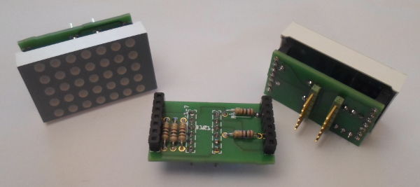
I intended the matrix to be activated a row at a time, so the resisitors are on the column pins. The data-sheet for the matrix is somewhat ambigious as to what current it should be permitted to draw. The electrical & optical characteristics mostly quote 20mA per dot as the “condition” they are based upon, and the absolute maximum per-dot power dissipation of 78mW works out at 30-37mA, but there is also a quoted maximum forward current of 30mA per chip. Assuming Vcc of 5volts the 390Ω resisitors I mostly used will permit 6-8mA, which is 4 of the 5 dots per row continually on.
Solderless prototype
This whole LED display project started out as a test of the LED matrix module boards I had made, which in turn also involved trying out PNP transistors driven by a PCF8574, and then evolved into the proof-of-concept this article is based on. One I/O expander controls transistors that power matrix rows, and another expander acts as current grounding for columns, both of which are wired to the same I2C master. Being proof-of-concept the circuit was driven with a PC controlled I2C master rather than a microcontroller.
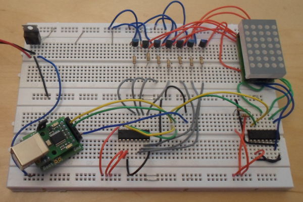
Originally the transistor emitters were attached directly to the unregulated 9 volt power supply rather than the 5 volt power rail, but as it turned out the “off” state of the I/O expanders still allowed enough current to flow to faintly light the LED dots that were supposed to be off. Think this is a combination of the pins being at Vcc which would have been around 5 volts rather than the 8-9 volts needed to turn off the PNP transistor, and the high gain that magnified the leakage current. I was reluctant to put in pull-up resisitors as they probably would have indirectly short-circuited the voltage regulator. Five columns is not much to work with, so below the design will be extended to multiple LED matrices in a row.
Column driver board
This board connects together three LED modules, and two 8-bit expanders (not installed into the IC sockets in the picture below) provide the 15 low-side power connections for them. It is intended to be tiled horizontally, with the corresponding downward-facing pins on the left and right edges connected together. The high-side row power pins/tracks are passively connected, as these will be driven externally. A major constraint was keeping the width entirely under the LED modules, so that when tiled all the LED matrices form a continious strip, so it was helpful that all the columns connections on the LED module are on the bottom pin row. The I/O expander address selects, which are the two three-hole recepticles on the bottom edge, are connected to Vcc and ground via external wires.
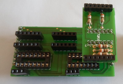
One thing of note is the is fanning out of parallel wires — the row power tracks — to multiple locations, which was done by making use of via holes that connects together tracks on either side of the PCB. When faced with a comparable problems with my first PCB I ended up using external fly-leads to get round the problem of tracks crossing, which by any measure was not a good solution, but at the time I did not know better. Using external wires for the I/O address selects is about as ugly, but in this case it was done to save space. Probably should have still put Vcc and ground recepticles, so the wires would not need to go between boards. For some mad reason I decided to order in a power-bar PCB to compensate for all of this.
The recepticles for the LED modules are a de-facto north-south divide on the board as there is little room between them for signal tracks. There is probably just about room to route the 7 row power tracks to the south side of the circuit board, but at the very least it would require a significant increase in board size to route tham to somewhere useful. This is something that will be addressed when I discuss an alternative architecture for driving LED matrices.
Row driver board
The task of this board is driving the pins that connect to the tiled column driver boards, most notably the high-side row power pins. It also contains the power supply, and in the original design was also going to contain a microcontroller to drive the I2C. Since this component board is a one-off, it was made using stripboard rather than a custom PCB. The PNP transistors I used have a maximum collector current rating of 100mA, which given the gain of 200 means a maximum base current of 0.5mA. The transistors also have an on voltage range of 600-750mV, which with a 5 volt power rail (i.e. a voltage drop of 4.25-4.4 between the base and ground) means a current-limiting resistance of 8K5-8K8Ω (8,500Ω to 8,800Ω) is required. I used 12KΩ (limits collector current to 72mW) as it happened to be the next-highest value of resistor I had sufficent stock of.
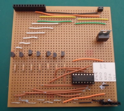
I think 70mA is rather underpowered for 9 LED modules (i.e. 45 dots in a row), so in hindsight I should have used some higher-power transistors rather than my stock of 500mW ones. In the prototype circuit the current flowing from the transistors was insufficent due to excessive base resistance, which is something I rectified for the driver board, but the sustainable load is still an issue. This is all due to ordering in stock before really understanding it, which is an inherant hazard to this experience-driven way of learning electronics. Nevertheless the circuit works, which is the important thing. Stripboard is something I also do not really enjoy using, but that is something I will address later in this article.
Refresh cycle
From experimentation the total refresh time needs to be at most 25ms, and within each refresh cycle the following two things are done as part of each row blinking:- Column update
- This is when updates are sent to the I/O Expanders on the column driver boards. This has to be performed with all the rows switched off to avoid vertical smearing, and is directly a function of I2C transaction time.
- Row enable (duty cycle)
- This is the flashing of the dots by having the row switched on. The duration of this affects brightness, and from trial-and-error needs to be least 40% of total cycle time. This is a function of the somewhat cautious current allowances.
Conclusions & Hindsight
LED displays — and more generally information displays — are not exactly the most imaginative of projects, but they do rather nicely provide a good context to bring together various different techniques. Here are some thoughts I have from doing this little project.
Optimal PCB density
Most of the project is via custom PCBs, and on the whole they make efficent use of space. The LED modules are just large enough to accomodate the LED matrix, with much of the space in between the headers is used for resisitors and data tracks. The I/O expanders can sink 100mA continiously (25mA per data pin) which is unusually high for an IC, so the column drivers did not need any transistors or resisitors. Microcontrollers would have to drive transistor switches, which would require much more PCB real-estate, and one thing I wanted to do was keep cost down.Soldering stripboard
At least compared to PCBs, which I have noted previously, I find working with stripboard a complete pain. A lot of the effort is putting in all the wires, and unless things are really spread out problems seem inevitable. As a rule-of-thumb I found that wires that are not supposed to be connected should be seperated by at least one unoccupied hole, which results in a low board density. Putting more than one IC chip on the 10cm-by-10cm strip-board I had stocked is quite a squeeze, given the number of connecting wires required.Component quality
So far I have not really paid much attention to the metals used in things I have soldered, but I suspect some are not really suitable for soldering. The wires, pin strips, and some of the recepticles were bought off E-bay — not a surprise as for instance I got ten 40-way pin headers for £2.30 rather than just one 16-way pin header for €1.90. However solder did not seem to flow onto them as smoothly as the components I sourced from the likes of Farnell and Maplin, probably because they were not really made for it.Using I2C
The base 100KHz clock speed the I/O expanders use means that the two-byte (i.e. 20 symbol) frame should take 0.2ms to transmit, although timestamping has indicated that the Python-controlled USB-based I2C master I was using actually took 3.5ms, and anecdotally there is about a 15ms budget within the refresh for transactions. This works out at a bit above four transactions, which is only enough for a single column drivers board. Using a microcontroller rather than a Python script running on a PC might well allow much more transactions within this 15ms budget, but in the absence of such evaluation the conclusion from the result here is that I2C is not suitable for high-speed refreshes.Cost
Cost control is something I've discussed in the past, in part because at the time I felt like I was constantly going out to buy more and more stuff, but these days feel I am now on top of knowing what to order in. Although the circumstances in which I learned the skills were less than ideal, the ability to source components and where from is something I learned back in Bristol. Acquisition was not on my job description, and with hindsight it should not have been a responsibility put upon my shoulders given how much stuff was being ordered and how much the project mattered to the company, but it gave me confidence in due-diligence. The single biggest skill is keeping track of product codes & names, and years later I feel this self-organisation has served me well.The prices
Below is an itiniary of most of the components used in this project. It does not include things like the cheap pin header strips & wires I bought off E-bay, but in cost terms it covers the vast majority of spending. There are discounts for bulk buying, but for most of the items here I only bought 10-25 units, which does not usually attract a significantly lower price.
| Item | Unit cost | Quantity | Total |
| LED module PCB | €2.26 | 9 | €20.34 |
| 390Ω resistor (Farnell) | €0.0246 | 45 | €1.10 |
| Column driver PCB | €6.00 | 3 | €18.00 |
| 3-way recepticle (Farnell) | €0.189 | 7 | €1.32 |
| 6-way recepticle (Farnell) | €0.749 | 18 | €13.48 |
| 8x2 IC socket (Farnell) | €0.17 | 7 | €1.20 |
| I/O expander (Farnell) | €1.50 | 7 | €10.50 |
| 2-way short recepticle (Farnell) | €0.87 | 1 | €0.87 |
| 2-way tall recepticle (Farnell) | €0.38 | 1 | €0.38 |
| 7-way recepticle (Farnell | €0.86 | 18 | €5.49 |
| 10cm-by-10cm stripboard (Farnell) | €2.95 | 1 | €2.95 |
| Voltage regulator (Farnell) | €0.89 | 1 | €0.89 |
| PNP transistor (Farnell) | €0.075 | 7 | €0.52 |
| €87.04 | |||
So all in about €90, which is an OK price given that the project consists of modules that can be re-used for other projects. The price profile has some particularities, which are noted below.
Cost oddities
I mostly order things in from Farnell in the UK, who seem to have free shipping to most of Europe, and have most of the items I am interested in. I have also used RS and Digi-key in the past, although Digi-key is a little steep on the shipping charges unless you buy $50 or so at once, in which case you get screwed for import duties half the time.- Resistors
- These are usually cheap anyway, generally only costly 4-5 cents, but the 390Ω ones are from a stock of 500 I bought a while ago. I bought an assorted resistor pack from Maplin, so I have a range of resisitors in stock, and bulk-buy the ones I tend to use.
- Recepticles
- Header recepticles are surprisingly expensive, accounting for a third of the total cost, and it could have easily been higher. The 3-way ones I recently restocked in bulk (150 for €28.41 — €0.66 each in smaller quantities), but the others are still rather expensive regardless of quantity.
- PCBs
- The PCBs account for a bit under half the total cost, but I feel the unit price is quite good for what they are. Typically around 30¢ per square centimetre, and due to how fabrication is charged they consist of modules can be re-used in other projects. The one thing I successfully avoided with this project was spending €30-50 on a single-use PCB.
- Integrated circuits
- A significant cost, but one where I think the unit cost is reasonable, and I was able to secure a reasonable 20% discount due to the quantity I ordered. With ICs there is typically one large drop in unit price with orders of 5-10, but beyond this further discounts involve quantities I would not realistically use.
Alternative design
As discussed I2C might not really be suitable for time-critical refreshes, which naturally bring questions about alternative designs. Having already done a lot of LED-display related stuff so far I am disinclined to make another project from scratch, but I did however rough-out a SMD-based PCB where row and column driving is integrated into a single 3-display board, and this is shown below.
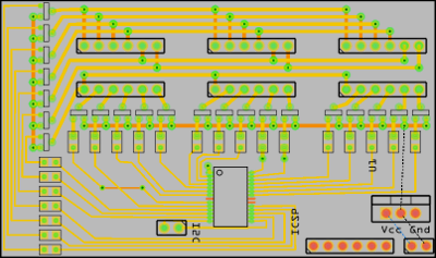
This design is based around a SSOP form-factor of the PIC16F886, and being SMD I don't consider myself experienced enough to actually build such a circuit, but as a design exercise I quite liked it. The circuit is clearly incomplete but it also highlights a few issues:-
- North-south divide
- As noted with the column driver circuit, the three pairs of headers for the LED modules don't allow much room for tracks to cross due to occupying both sides of the PCB, and this is an issue if the board is to be narrow enough to allow tiling. Even if all the resistors & transistors on the left-hand side were moved upwards, it would be difficult to route all the signal wires in the space between the header receptacles. Main problem is how much space via holes need.
- Space for tracks
- A lot of space is needed just to get signal tracks to where they need to go, which is something the use of I2C expanders in the first place was intended to avoid, and this brings me back to why I abandoned my earliest LED grid attempts. Anything other than a single-chip solution seems self-defeating.
- Transistor space usage
- Even with SMD, the space needed for switching transistors and their associated resistors is significant — about a quarter of the PCB space, and this design is not even complete. The SMD transistors I have come across have a gain of around 100, so I suspect even the aggregate base current requirements will exceed the microcontroller's current source/sink limits. At least for the row power lines, paired transistors are likely needed.
- Programmability
- Whereas through-hole microcontrollers can be programmed in a chip programmer seat before final installation, the same thing cannot really be done with SMD controllers. This means having a space budget for in-circuit serial programming infrastructure, which is another 5-10% of PCB real-estate.