RS232 line driver
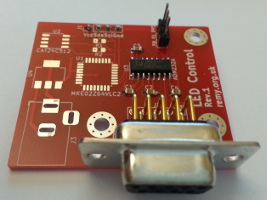
08 January 2020This article is an effective rewrite of my original 2017 RS232 wire-line article, updated to be made clearer and use a PCB rather than breadboard. The circuit board featured is one that had RS232 as a communication interface serving a higher purpose, but due to a major flaw in the design it could not do what it was originally intended for, and eventually I decided to abandon the design. However the PCB included debugging headers so it could still be used for demonstrating RS232 line driving rather than going to waste.
The circuit
The intended purpose of the PCB was a controller and power supply for several LED dot-matrix tiles, where the display data could be loaded in via a D-Sub serial port operating at full RS232 voltage levels, and stored in non-volatile flash memory. The schematic for this circuit is shown below. However for some reason no connection for a programmer was included, so in this instance only the RS232 sub-circuit is used.
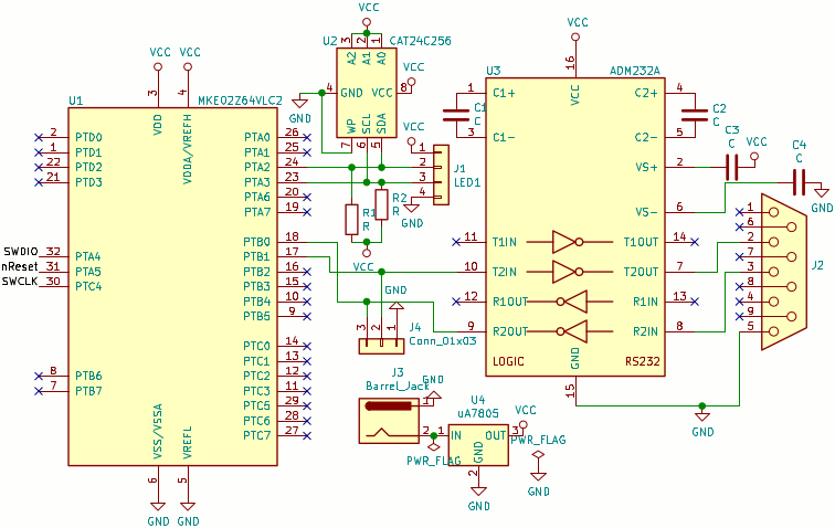
The Kinetis KE02 is overkill in terms of pins for this circuit, but at the time it was designed I had no experience of the smaller KE4 and the extra PCB space was not an issue.
When I subsequently made a Kinetis KE04 based I2C master I gave it a pin-out that intentionally matches the matrix tiles so that it could be used as a stop-gap firmware development platform.
I originally opted for the Kinetis series because they were 5-volt capable, but since I have found converters that can bridge 3.3-volt and 5-volt I2C buses I am considering switching to using an NXP LPC11Uxx family microcontroller due to its native USB support.
RS232 line driver wiring
My picture of a working RS232 driver setup was a great help when designing the schematic for this circuit, although due to its resolution I had to cross-reference with other sources such as the data-sheets. Because of this headache I have summerised the connections in the table below — TTL indicates which connectors on a TTL-level adapter should be attached, and RS232 the pins on an RS232 port.
| TTL | Ground (Black) | Tx (Orange) | Rx (Yellow) | |||||||
| ADM232A | Pin 1 | Pin 3 | Pin 4 | Pin 5 | Pin 2 (V+) | Pin 6 (V-) | Pin 16 (Vcc) |
Pin 15 (Ground) |
Pin 10 (T2In) | Pin 9 (R2Out) |
| 0.1μF | 0.1μF | 0.1μF to Vcc | 0.1μF to Ground | Pin 7 (T2Out) | Pin 8 (R2In) | |||||
| RS232 | Pin 5 (Ground) | Pin 2 (Rx) | Pin 3 (Tx) | |||||||
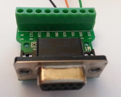
One problem I met is that, unlike something along the lines of the bus-based I2C, it is easy to get mixed up with transmit and receive when wiring things up — for instance when something is labelled transmit does it refer to the local perspective, or whether it is where the remote transmit line should be connected. For instance the breakout adapter below lists Pin 2 & 3 as RxD & TxD respectively, which corresponds to the DTE (male) pins of whatever is connected to the adapter, rather than the DCE (female) pins on the adapter itself.
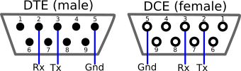
The underlying problem is that at some point a cross-over between transmit and receive is required, and this is normally accomodated for by the male and female connectors having different pin mappings, as summerised in the images below. However it is all too easy to either omit or duplicate the cross-over, and this is a common problem with RS232.
Circuit flaws
The circuit does not include connections for programming the microcontroller, a mistake that makes be wonder where my thinking was when I laid out the schematic. In order to amortise shipping costs I often batch together multiple designed into the same order when using Seeedstudio, and since they were doing a special offer in top of already low unit prices, this circuit was one of four in the same order. In hindsight I feel that I rushed them, and the only reason I did not make more mistakes was because the other circuits were based on strip-board prototypes. To make matters worse this circuit was the first that I designed using KiCAD 5 rather than KiCad 4, and being a shake-down project attention would have been diverted away from the circuit itself. All these added together is a recipe for carelessness.Closing remarks
In hindsight I felt that opting for an RS232 physical interface was really just for sake of using it, which in turn was probably influenced by wanting to check out the PCB footprints for the D-Sub connector. Since I included pins to get at the TTL-voltage RS232 signal it was possible to use the RS232 sub-circuit independently of the microcontroller, and I eventually decided that it was best to have an article dedicated to just this sub-circuit. I think RS232 line drivers and connectors are rather expensive and in any case I would end up using an external USB-RS232 adapter anyway, so may as well just have USB on the circuit itself.If it was not for the background effort in clarifying the RS232 line driver wiring, I probably would have abandoned the circuit entirely and discarded the draft article. Furthering my LED matrix display system is a backlogged project which quite likely will be on hold until at least the second half of the year, by which time I may well be redesigning the control circuit from scratch. In the mean-time I have been having a clear-out of loose ends such as half-written articles, either spinning out the written content or dropping them entirely.