Thermocouple control
31 July 2020I had been doing some temperature tests with a portable hot-plate I had just obtained but I was finding that using my infra-red heat gun was a bit of a pain when trying to write down values at the same time. Partly in response to seeing various videos of cooking devices modded for automatic reflow soldering I decided to order in some thermocouples and build a circuit that would allow a laptop to record the temperature readings. I am not yet planning to mod my own hot-plate but this circuit is part of experimentation that is certainly on the path towards doing so.
Normally I would have started out by mounting individual components onto breakout boards and used things such as my I2C adapter so that the control software would be a Python script on my desktop rather than firmware on a microcontroller, but I was over in the UK at the time and hence did not have access to all my equipment.
Thermocouple devices
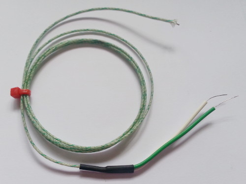
When choosing a thermocouple I pretty much went for the cheapest that had a maximum temperature of 350°C, and this was the LabfacilityZ3-K-1M K-type shown below.
The hot junction is exposed at the end of the glass fibre sheath and I am guessing the cold junction is within the black heatshrink at the bottom of the picture.r
Thermocouples actually measure the temperature differential along its entire length although in practice only the part towards the hot junction will be near the heat source being measured.
I did not have a sensitive enough multi-meter at hand to test the thermocouple before putting it into a circuit since the voltages induced are barely into the milli-volts.
Various value tables are out there to convert between voltage and temperature although I also found a Python module which is much more convenient for my purposes. Within the zero to circa 250°C temperature range I am interested in there is about a 1% deviation from a linear approximation of the data points, but this is of limited use on microcontrollers without a floating-point unit.
Controller circuit design
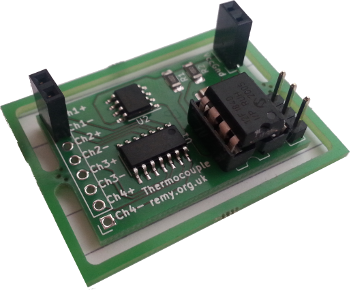
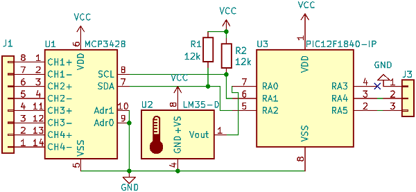
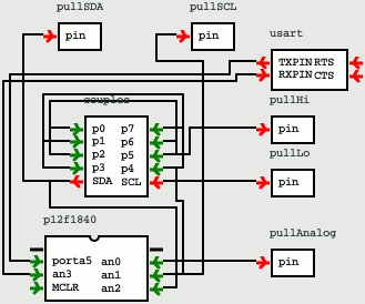
The circuit is somewhat experimental as it was put together on a Sunday afternoon, but as can be seen from the circuit schematic below it is not particularly complex — a microcontroller and two auxiliary chips, together with the pull-up resistors for an internal I2C connection. Up to four thermocouples are connected on the left-hand side and a serial connection to a computer is connected on the right-hand side. For clarity the power connection has been omitted.
From the outset I planned to open-source the hardware design of this circuit so for better or worse I decided to only use symbols from the KiCad library. The list below gives an overview of tasks that individual components perform:-
- Thermocouple voltage reading
- The ADC (Analog-Digital Conversion) built in to PIC chips is not suitable for the sub-millivolt accuracy needed to read thermocouples so an external Microchip
MCP3428ADC chip is used for the task. The digitised voltage levels are read over an I2C interface, and I opted for the variant that has four channels. - Reference temperature chip
- Thermocouples measure a temperature difference between two junctions, so for an accurate calculation of the temperature at the probe junction, the temperature of the other junction needs to be known.
Rather than assuming a room temperature of 20-25°C the circuit includes a Texas Instruments
LM35-Dtemperature sensor that provides a calibrated reference temperature, which it outputs as an analog signal. - Communications microcontroller
- A Microchip
PIC12F1840is used to take the digitised voltage reading and the analog temperature reference, from which is calculates the actual temperature of the probe end of the thermocouple. This is then output on the RS232 connection. I had thought about providing USB interface but for simplicity I decided to expose the TTL-level RS232 signals directly. - Power connection
- For simplicitly and to save space an external regulated power supply is assumed rather than having an on-board regulator. This also allows easy switching between 3.3-volt and 5-volt operation.
RA0 (Pin 7), which precludes having in-circuit programming unless there was a way of isolating the pin.
The pull-up for the I2C clock on RA1 (Pin 6) would also be problematic.
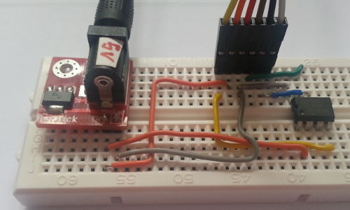
As a result I opted to use a socketed through-hole microcontroller which would be programmed off-circuit, and since I did not have my programming seat with me I used the make-shift circuit below.
Originally I planned to use the PIC16F1823 which is a 16-pin chip from the same family as the PIC12F1840 but only the latter had a symbol within KiCad's built-in library.
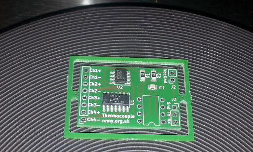
Fabrication and population
I used Aisler to fabricate the PCB purely for the fast turn-around time and in this instance the order I put in on Sunday night was shipped on Wednesday and arrived the following Friday. For the surface-mount components I did a reflow using some MG Chemicals4902P-15G solder paste, which has a composition similar to the Chip Quik I have used in the past but was significantly cheaper — I will write a review of this paste once I have used it on a larger PCB.
The reflow itself was done using a newly-bought portable hot-plate as shown below, and being a small PCB on an ultra-clean hob I dispensed with my usual steel plate.
In the past I was not impressed with various lead-free solders I had ordered in compared to my usual lead-based stock, but in this instance I used Edsyn SAC35100 95.5/5/0.7 Tin/Silver/Copper.
The ultra-thin 0.35mm diameter melts very easily and it has the same rosin core as my usual Edsyn SS5250 although I need to use it a bit more to get a better opinion of it.
Writing the Firmware
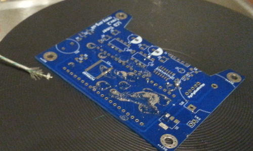
A large portion of the development was done in gpsim using the circuit shown below, partly in order to get back up to speed with PIC assembly, and partly due to the lead-time in ordering in the PCBs and components. While the gpsim circuit is not a complete representation of the physical circuit it was pretty close — close enough that by the time I had built the hardware, the only change needed to make everything work was fixing up the I2C transactions to get the external ADC to respond properly.
Since it had been well over a year since I last did any PIC programming and hence was a little rusty, my original plan was to just use the native 8-bit word size of the PIC12F1840 since I had forgotten the details of things like the INDFx indirect memory access registers and the carry/borrow bits which would be needed to implement 16-bit variables.
However by the time the hardware was ready I had already made significant progress on a second revision of the firmware and the first was never used.
The second revision firmware is available from my PIC-Code Bitbucket repository.
PIC assembly language
Although a lot of my past projects were written in C I have long concluded that PIC microcontrollers really need to be programmed using assembly, which is a topic I have already covered in depth. Having been well over a year since I last made any real use of PIC assembly I got back into it surprisingly quickly, with most of the headaches I had in the process being down to the banked memory model. This was exacerbated because most of the special-purpose registers I used were all on the same bank, which made it all the easier to forget about the banking. Tricks I eventially remembered was the convention of always switching back to Bank 0 when returning from ”library” functions, and using the shared memory area which is accessible from all banks.Firmware parameters
Much of the process done by the firmware is analogue-to-digital conversions, and the parameters required to both measure the thermocouple voltage and the reference temperature voltage are described in the list below.- Thermocouple readings
-
The
MCP3428thermocouple ADC has both a configurable sample resolution and adjustable input amplifier, and for this circuit the maximum 16-bit resolution is used together with maximum Gain of8x— this gives a voltage delta of 7.8125μV which corresponds to 0.19°C, and representing the specified maximum 350°C (14.293mV) of the thermocouple would require 11 bits. Originally a Gain of 1:1 was used which gave a delta of 62.5μV and only the bottom 8 bits were taken given a maximum representable temperature of 389°C, but this resulted in intervals of 1.58°C which I felt was too big. - Reference temperature
-
Reference temperature readings are made by the
LM35DMsensor chip and are output as an analogue signal with a scale of 10mV per °C. This signal is digitised by the on-board ADC on thePIC12F1840which has a resolution of 10 bits and in this circuit has been configured to have a delta of 1mV giving a maximum reading of 1.024 volts. The middle 8 bits are used which gives a delta of 0.2°C, which is chosen because the chip itself has a specified accuracy of 0.25°C, and this allows a maximum reference reading of 50.6°C. This is reduced to 49°C to allow for an 8-bit to 8-bit lookup table, which also quantises to the same voltage delta as the thermocouple readings, as I felt that allowing for a wider range of values was an uneconomic use of chip resources. - Temperature reading conversion
- The measured 16-bit thermocouple voltage and the 8-bit converted reference temperature are summed, and a second lookup table is used to convert this combined thermal voltage reading into a final Celsius reading. Prior to lookup the lowest bit of this sum is discarded because there is not enough program flash for a full-size 1:1 table. The table has entries for temperatures upto 400°C which is the sum of the maximum reference temperature and the maximum specified thermocouple temperature, and the output value is in tenths of a degree.
8-bit lookup tables
The calculation for conversion between temperature and thermocouple voltages is something that PIC microcontrollers are not suitable for, so instead pre-calculated lookup tables are used. These tables were generated using a Python script that made use of the Thermocouples Reference module, which saved me from having to scrape the data from data-sheets provided by various organisations. For convenience I rolled in other conversions into the tables and as a result the firmware does very little actual calculation. The tables themselves are stored in the program memory as functions that make use of theBRW and RETLE instructions, as shown in the example code below:
lookupTable: BRW RETLW 1 RETLW 1 RETLW 2 RETLW 3 ; ...
The BRW instruction does a relative branch that corresponds to the index, and the RETLW it lands on is the associated value. I had thought about using EEPROM to store the tables, but at 256 bytes it was too small to be worth the hassle.
16-bit lookup tables
For lookups where one or both of the input or output are 16-bit values it is not enough to the the working registerW, and the approach I used was utilising the indirect registers which are essentially pointers.
There are a pair of registers FSRxH & FSRxL which specify the memory address that is pointed at, and using within instructions INDFx accesses the value at said address.
The PIC12F1840 has two sets of these, so lookup will use one for input and one for output.
lookupDegrees: ; Load index offset MOVIW 0[FSR0] MOVWF FSR1L MOVIW 1[FSR0] MOVWF FSR1H ; Add offset to table MOVLW LOW tableDegrees ADDWFC FSR1L BTFSC STATUS,0 INCF FSR1H MOVLW HIGH tableDegrees ADDWF FSR1H RETURN
The values pointed at by the first register set is treated as the offset so these are loaded as addresses for the second set, and then the offset into program memory is added. Note that since program memory is in flash it can only be read, not written. The data itself is specified using the RETLW instruction which has an 8-bit data section, and in this case two consecutive instructions are used for the lower and upper bytes of the 16-bit value.
tableDegrees: RETLW 0 ; 0.0000mV 0.00C RETLW 0 RETLW 4 ; 0.0156mV 0.40C RETLW 0 RETLW 8 ; 0.0312mV 0.79C RETLW 0 ; .. etc ..
I think other instructions can be used but I have not investigated this. The caller than can read the values directly:
MOVIW 0[FSR1] MOVIW 1[FSR1]
Usefulness and influence of gpsim
From an early stage I found gpsim to be a double-edged sword, because it had the convenience and observability of everything being in software but with it came headaches associated with its limited ability to represent real-world circuits. I certainly remember writing hacks into firmware for when it was being run under simulation rather than on actual hardware, and at least one debuggung session was caused by forgetting to remove the hack before using It affected my choice of chips and was used for several of my projects back in 2017 where it was instrumental in me working out how to use I2C/RS232 serial interfaces and LCD displays, but away from the latter things its usefulness was extremely limited. There are also significant bugs which in one or two cases made gpsim much more of a hindrance than a help, so aside from some profiling I have rarely used it in more recent years.Accuracy
Anecdotally I think the temperature reported by the circuit is an under-read by 1°C and I suspect it might be an issue with the reference temperature chip, but the readings in practice seem to be more stable than what I often get with the handheld infra-red thermometer. One issue is how long it takes for the thermocouple itself to heat up, such as in the hot-plate reflow scenario shown below — the response time is a little sluggish but at least it is predictable and it is hands-free. By experimentation I worked out the temperature reading that is optimal for turning off the heat even though I very much doubt it is anywhere near the true temperature of the paste itself.
I think the circuit is about as accurate as I can reasonably expect it to be, as proper calibration would require equipment I do not have at hand. In any case a consistent error is not an issue for my intended purposes, where other sources of inaccuracy are of much bigger concern.
Remarks
My electronics projects have been on a bit of a hiatus and almost all the other ones I have completed this year were actually designed last year, so it is very satisfying to have a circuit done start-to-finish in just under a fortnight. Two of the three other circuits I currently have in the works are projects that have been ongoing for months, and there is still the outside possibility that I will not complete them before 2021. In any case the next few sub-sections are thoughts I had in completing this temperature circuit.Using the PIC12F1840
In hindsight opting for the 8-pinPIC12F1840 rather than one of the 16-pin variants in the same family was a mistake, since it precluded using in-circuit programming. Yes it made it easier to open-source the PCB design itself, and I was able to do the vast majority of the firmware development using gpsim, but swapping chips in and out of the circuit is a pain. This was made worse by having to use a make-shift programming circuit since I did not have my programming seat with me. All circuits I currently have in the pipeline include in-circuit programming headers.
Issues with the MCP3248 ADC chips
It could well be a problem with my circuit design as not including sufficient bypass capacitance, or simply bad luck with one of the units, but I have noticed some flakiness with theMCP3428 ADC chips.
Basically one of them simply stopped responding to I2C transactions, and for the time being all I could really do was solder up a fresh board with a new chip — the second one initially showed the same symptoms but then a while later seemed to work perfectly ever since.
At some point I may desolder the faulty chip it and mount it on a breakout board for proper investigation, but considering these chips are £2.93+VAT each from a reputable dealer having to do this at all is something I felt has to be flagged up.