Chip programming seat
22 September 2017Flashing a firmware a PIC chip is done via a serial protocol, and most people will do this using an off-the-shelf programmer such as the PICkit 3. There are other third-party flashing devices available, and some people will roll their own, but PICkit 3 is the one I have used so far. An issue I have yet to write about until now is connecting the programmer to the chip being flashed. There are two main ways this is can be done: Using a programming seat, and in-circuit programming. The main point of discussion here is the former, one of which is shown below with a chip in place:
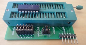
Programming seats — also known under alternative names such as programming adapter and universal programming seat — consist of a zero-insertion force socket that clamps onto the inserted chip, which are wired up to correctly route the programming signals for a variety of different sized PIC chips. They are available on E-bay for a few dollars, and are often bundled together with a PICkit & USB cable for a bundle price of around $15-25.
Using the programmer seat
The instructions that come with programming seat I got were pretty terse, and as shown below consisted just of what is printed on the underside. Chip location seemed obvious enough but the jumper settings I was not so sure about. ThePIC16F630 is DIP14 (i.e. 14 pins) so I assumed the line DIP8,14,28,20: J1:2/J2,J3,J4,J5,J6,J7:2-3 was the relevant one — I then guessed that J1 should be set to the middle pair, and that all the others should be set to the pins away from the chip holder.
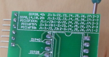
Using a multimeter I checked the connectivity of the slots of where I thought a 14-pin chip should go and the programmer interface, and what I saw corresponded to the inline programmer schematic shown in the PIC16F630 and PIC16F88 specifications. During programming pins not involved in the programming process are switched to high-impedence input mode, so the fact that the programming clock and data signals will be routed to other pins — a side-effect of the chip seat accommodating multiple pin layouts — is not an issue. It is only Vpp (routed using J1) that has to go to the right place, as programming can raise the pin to 13volts, and this is sufficent to blow the chip if it is connected to any of the other pins.
Programming power requirements
The PICkit can itself power the chip during programming (although for some reason within MPLAB IPE the option takes some digging to find), but I found that in practice the PICkit reported insufficent voltage every time I tried it, and hence it always needs external power. It is supposedly due to the power requirements of the flashing process pushing what USB is able to supply, but it could just as easily be an issue with my particular PICkit, or most likley a combination of the two. Either way patching in an external 5 volts of power solved the issue, and for convenience I made myself a small power supply board that sits between the chip seat and the PICkit.
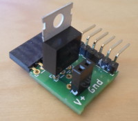
The board includes its own power regulator so I just hook up the power terminals to a 9 volt power cell.
In-circuit programming
Rather than programming a PIC and then inserting it into a cicuit, the circuit itself can also be wired up with a socket that allows direct attachment of the PICkit. This does place some limitations on the circuit, and the usual recommendation of not sharing the pins used for programming as often as not is impractical, but contray to my initial expectations in-circuit programming turned out to be my preferred way of connecting a programmer. The one-off overhead of wiring up the socket for the programmer connection turned out to be preferable to complications caused by repeatedly moving the chip between a curcuit and the programmig seat.With the LCD display project which was my first serious circuit there were no issues with having to share pins, and since it was also built before I got my power-supply board (above) I would have also had to worry about manually wiring up external power to the programmer seat. All in I had a desire to make this circuit self-sufficent, in order to keep all complications in one place, so it even provided the power needed for flashing.