USB-I2C adapter
28 October 2018This is a USB-based I2C master which is derived on my earlier prototype Serial-I2C adapter. I normally use the Robot Electronics USB-ISS I2C adapter for test purposes requiring a PC-controlled I2C master, and development of my original RS232-driven I2C adapter was a response to problems the USB-ISS had working with Cypress I/O expanders. Since then I have noticed that the USB-ISS having problems in other situations that the Serial-I2C adapter was fine with, so decided to create my own USB adapter.
To be fair the problems with the USB-ISS could well be down to use-and-abuse damage, but my own I2C adapter is more in tune with my use-cases — the main thing is the much more detailed response codes in error situations, which are intended to aid debugging, and the exclusion of non-I2C functionality negating the need for any setup. The command protocol is also intended to more accurately reflect the underlying I2C transaction, in order to aid the quick tracking of problems.
Circuit design and layout
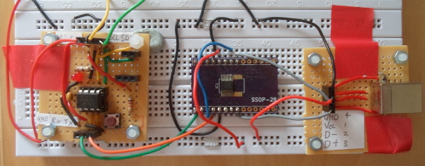
When I was experimenting with the Cypress I/O expanders, I created a make-shift bread-board circuit that needed just a single USB connection, rather than an external power supply and an RS232 converter cable, and this is shown below. The PCB is basically a size-reduction of this make-shift setup, due to the inconvenience of taking it with me when I last went back to the UK.
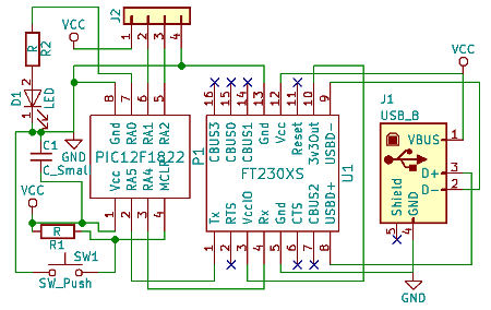
The circuit schematic shown below is a direct copy of this make-shift setup, the most notable omission being any form of on-board pull-up resistors on the I2C clock & data lines. The I2C-RS232 breadboard included receptacles for interchangeable pull-ups but I found these to not be of much use in practice, and thought it best to simply leave pull-ups to the external circuit. The reset button and activity LED were not really required, but I decided to include them anyway to maintain the functionality of the original breadboard.
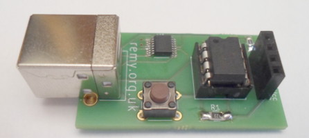
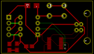
The PCB layouts is shown below, where red tracks are on the top layer and green ones one the bottom layer. What is immediately noticeable is how close this board is to being single-layered, with only four tracks on the bottom layer, but eliminating all of them would be difficult. In any case it would be moot since there is no fab cost savings in having just one layer. Most of the tracks are far thicker than they need to be, but in this circuit the space tracks take up is not really an issue.
PCB screw-ups
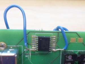
Although not shown in the images above, I sent an earlier version of the PCB for fabrication that had a major flaw: The Data+ and Data+ connections between the USB connector and the USB-RS232 chip were the wrong way round. Unlike a comparable mistake on another PCB that was rectified simply but cutting some tracks, this mistake would require new connections to be made as part of the rework, and as can be seen below this meant soldering wires in a way that is not exactly robust:
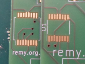
The rework fixed the PCB, verifying what the problem was, but it was plagued with unreliability — some of the time Linux recognised when it was plugged in, but it was undetected often enough that I decided to give up on the rework, and wait for the rectified PCB to arrive from fabrication. I also decided not to root-cause whether the unreliability was a problem with the rework or prior damage to the chip itself. However there was a second fault that still affected the reworked PCB, and that was the footprint being slightly wide — basic testing of the UART with these boards suggested problems with the electrical contacts, so I ordered a third revision of the board, which is compared with the second revision in the image below:
In hindsight the third revision was probably not necessary, as indications are that I had a bad batch of USB-UART interface chips, rather than problems with electrical contacts. The Gerber files for this third revision PCB are available in the download section of the Bitbucket repository, and most fabs will take the zip-file as-is. It is however made available without any warranty.
Alternative USB interfaces
A while back I ordered in aPIC16F1454 (Farnell 2305809) which included USB support, but it was pretty clear that utilising this USB support would be a major project. The data-sheet section starts out by stating that a background in USB is expected, and the next page lists the fourteen registers used to control the USB module. The subsequent 25 pages are dotted with USB terms such as single-ended zero condition that one would only know having read the USB standards documents, which at time of writing I did not have copies of, and have the sneaky suspicion may not be freely available. I also picked up a Microchip MCP2221A (Farnell 2678459) but on the controlling PC an application would have to implement a communication protocol with the MCP2221A rather than reading/writing RS232 bytes directly.
Circuit build
Getting this PCB working was much more difficult than it should have been, having sent three revisions for fabriction. In total I ordered nine PCBs, six of which I at least partially soldered, and in the end only two of them worked properly if at all. I thought this would be a simple circuit, but considering how few actual components it had and that most of them I had used before, it was something of an ordeal.Dodgy UART chips
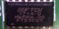
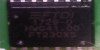
Many of the PCBs I soldered up just had the USB socket and the UART interface chip in place, and whether Linux would recognise the device or not was temperamental at best. At first I thought it as dodgy connections, but in the end I concluded it was a dodgy batch of interface chips, because all the malfunctioning PCBs had one thing in common: They all had units with a manufacturing date code of1729-D, whereas the chip used for the prototype had 1714-D — the latter was from an earlier order of just three chips. The two stocks were stored in the same folder sleeve, so I doubt it is any fault with handling. on my part.
Status LED
I have not used surface-mount LEDs before, but other than difficulty seeing the polarity marking, was no different to hand-soldering capacitors and resistors. I used an Osram Red LED (LSR976, Farnell 1226392) since it was of the right size and I had it in stock. The LED was rated as 25mA, but I decided that I wanted it to draw only 5mA at most — the LED had a reported voltage drop of 2V, so being a 5-volt circuit I aimed to have a protective resistance of at least 600Ω. Since the nearest ones I had to this rating of the correct physical size (0805/2012) were 560Ω and 820Ω I opted for the latter. The LED seemed quite bright considering it was rated at 25mA and I was giving it only 3-4mA.
Decoupling capacitor
The design included a decoupling capacitor from the outset, but what surprised me was that thePIC12F1822 did not work at all until it was installed. It is unusual these days for me to omit such capacitors, but I have used this micro-controller without them in the past in similar setups involving I2C and RS232. Suppose in the past the capacitance within the circuit itself was enough, so it has not caught me out before.
Firmware serial protocol
The firmware for this I2C master, which is available within my Bitbucket repository, is the same code-base used for the previous Serial-I2C adapter, although it has been updated since the article for the latter was published. The serial protocol has been slightly updated since being originally defined, but this only affects transactions that under the old protocol would have failed — the maximum amount of data that can be transferred has been increased, and the error code returned in certain circumstances has changed. The updated protocol is summarised in the table below:
| Slave addr | Mode | Register | Register | Count | Data |
| LSB is read bit | 0, 1, or 2 | Modes 1 & 2 | Mode 2 only | 0-60 | Writes only |
The mode is the number of register address bytes and at least for writes how the mode & register bytes are handled is the same as how the count & data bytes are handled. The return value sent back to the host via RS232 always includes at least two bytes: The first is a success/failure indicator, and the second gives further information. On success the first byte is 0x01 and the second byte gives the number of bytes read/written; for a successful read subsequent bytes are the read data. On failure the first is 0x00 and the second byte gives an approximation of the command byte the transaction failed on:
| Error code | Mode | 0 | 1 | 2 |
| 1 | Invalid mode | ||
| 0 | No slave address Ack | ||
| 2 | Overrun | Reg Nack | |
| 3 | Data Nack | Overrun | Reg Nack |
| 4 | Data Nack | Overrun | |
| 5-64 | Data Nack | ||
| 65-254 | not used | ||
| 255 | Restart address Nack | ||
An overrun is when the requested data byte counts is larger than what the internal buffer can accommodate. A restart address nack is when a nack is received in response to the slave address after the I2C Restart in a read transactions that includes register addresses — this is because such transactions are a combined write and read, which involve the master sending the slave device address twice, and a failure with the second sending of the address is a problem other than the address possibly just being incorrect.
Python control script
Since this PCB is intended as a replacement for the USB-ISS I used in the past, I modified my original Python test program and this modified version is included within Bitbucket. The command-line reflects the serial protocol, and the following templates show typical usage. A notable change compared to the control script for the USB-ISS is that while read requests still need to specify the number of bytes to read from a slave device, the number of bytes the script itself reads from the adapter is handled automatically.ttyI2C.py /dev/ttyUSB0 <addr> 0 <count> [byte(s)] ttyI2C.py /dev/ttyUSB0 <addr> 1 <reg1> <count> [byte(s)] ttyI2C.py /dev/ttyUSB0 <addr> 2 <reg1> <reg2> <count> [byte(s)]
The serial port requires a BAUD rate of 57,600 which is set by the control script. You may also need to set read/write permissions on /dev/ttyUSBx as quite often serial devices are not attached with global access.