ARM I2C Master
01 December 2019Back in 2018 I built myself a prototype RS232-driven I2C master as a last-ditch effort to get a troublesome I/O expander working, and later that year I developed this prototype into my own USB-I2C adapter. The development was rather protracted involving three PCB revisions, and in the end I don't think I used the adapter much in subsequent projects. This circuit is a reimplementation of the adapter using an ARM-based Kinetis E microcontroller rather than a Microchip
PIC16F1823, although in this case creating a new adapter was a means to test components I had not used before, before trying them on much larger circuits.
RS232 vs. USB native
When I made my previous adapter I had thought about using alternatives to RS232 converters in order to provide a USB interface to a circuit, but I was not impressed with the alternatives I came across, finally concluding that the effort was not worth the outcome. In practice all I really needed was a basic serial connection that I could use from a computer and RS232 suited my needs fine — the only issue was limits on speed I could get out of my favoured PIC microcontrollers, and possible headaches if more than one serial-based device was connected to the same computer. I do plan to look at using native USB support, most likley using a chip from the NXPLPC11Uxx series, but that is beyond the scope of this article.
Component trials
The main purpose of making this board is to try out various new hardware components I have not used previously, and these are listed below — in all of these cases a major thing was to verify that a given component fits with a given KiCad footprint, although physical properties were not the only thing I was checking for. I like to try out components individually before committing to use them in larger-scale circuits.- Kinetis KE04 microcontroller
- The Kinetis
MKE04Z8appears to be a smaller version — in terms of pins and memory space — of the Kinetis KE02 series I have already used, but I still wish to try it out before committing it to it for any major project. Trying it out is the only truly reliable way of checking the extent of firmware compatibility as just comparing user manuals is prone to mistakes. - Mini-USB connector
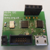
- Even though I have had a stock of micro and mini USB connectors for quite some time, I have so far opted to only use the bulky USB type-B connector which appears to have a single standardised PCB footprint, rather than mini- and micro-USB sockets that seem to be manufacturer-specific. These days I find obtaining and carrying around full-size cables to be a pain, so decided it was time to make the switch to the smaller form factor.
- 10-pin mini-ITC receptacle
- So far my ARM-based PCBs have used programming interfaces that have taken a disproportionate amount of the PCB real-estate, and in practice I found my six-pin custom connector to be bit of a pain. ARM specifies a 10-pin 1.27mm pitch IDC connector as a standard interface and there are off-the-shelf adapters such as the Olimex
ARM-JTAG-20-10, but I only recently sourced a matching receptacle for it. KiCad did not have a footprint for it so I scaled down the footprint for the 2.54-pitch receptacle. - External clock
- Unlike other microcontrollers I have used the Kinetis series does not provide a specified off-the-shelf clock frequency, which in turn causes issues with things like RS232 which need a known clock frequency in order to calculate parameter values. I had thought about using the crystal setup I was familiar with, but in the end decided to go for a self-contained external oscillator instead.
- Unfiltered USB power supply
- My previous I2C adapter was the one instance of one of my circuits not working without a by-pass capacitor, which at the time I put down to my usual prototyping boards having buckets of parasitic capacitance, but on hindsight was more likley due to the stability of the power supply USB provides. The FTDI
FT230XShas its own built-in voltage regulator, but I wanted to see if other components could cope with unregulated USB power.
Circuit design
The schematic for the main part of the circuit is shown below; for clarity some components such as the external connectors have been omitted, but the labels present indicate all the important connections. These days I prefer using labels rather than wires, even though the result is less impressive-looking schematics.
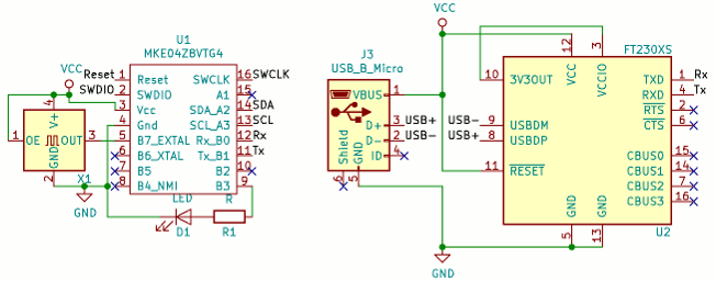
Schematically the bypass capacitors were attached to the power rails rather than the corresponding pins on the components, so they do not appear above. Remarks on things not already covered in the component trial section are listed below.
- External power connector
- I wanted the ability to use a power supply other than USB when programming the KE04 chip, so I included this power point which I could plug one of my mini-power boards into. It also makes it possible to use the PCB as a non-USB breakout for the Kinetis chip, should the USB interface prove problematic.
- Tie-down of the FT230 reset pin
- I had suspicions that the USB-RS232 adapter chip does not have an internal tie-down on the reset pin, so I felt it best not left floating. It is possible that random effects of floating pins is the real reason behind what I have previously put down to a bad batch of chips.
- FT230 power supply
- The FT230 chip actually requires a 3.3 volt power supply but it has its own built-in power regulator that is used in 5 volt circuits such as this one. This is clearly due to the expectation that it would be powered directly via USB.
- TTL-level RS232 taps
- This started as an experiment in seeing how circuit changes can be made directly in PCBnew rather than making a schematic change that is propagated via a netlist change. Given the amount of trouble I have had with the RS232 converter chip in the past, I wanted somewhere I could easily tap the TTL-level RS232 for testing purposes.
- Pull-up resistors
- When testing I2C components having to provide external pull-up resistors is a pain, which is a major reason I ended up using the Robot Electronics I2C-USB adapter rather than my own, even though the latter had known problems. For this iteration I included on-board pull-up resistors so that the adapter can drive I2C devices without needing a make-shift circuit in between.
- Status LED
- Nothing special here. It is always useful to include an LED because it provides a fall-back indicator that can be used to flag up problems with firmware becoming jammed.
- No reset button
- A notable omission compared to the previous PIC-based adapter is the lack of a reset button. This was a carry-over from the breadboard prototype and I felt that it was redundant. Its removal helped make the new PCB substantially smaller.
Bill of materials
Although I provided cost information for my earliest circuits, since then information on costs have been limited to remarks on specific components I bought in bulk. For this adapter I deciced to provide a full list of components, and this is shown below. The PCB was ordered from Aisler and the 16MHz oscillator from Mouser, whereas all other components were sourced from Farnell. Farnell is still my preferred supplier although there are a few things I find irritating about them, one of them being uncompetative pricing of some items they stock.
| Part name | Manufacturer | Part number | Order code | Price (ex. GST) |
| Kinetis KE04 (TSSOP) | NXP | MKE04Z8VTG4 |
2409294 | €1.06 |
| USB-RS232 converter | FTDI | FT230XS-R |
2081321 | €1.78 |
| 16MHz oscillator | Epson | SG5032CCN |
732-5032CC16.0HJGA3(Mouser) |
€1.06 |
| MicroUSB B connector | Amphenol | 10103594-0001LF |
2293752 | €0.483 |
| Programming connector | Samtec | SHF-105-01-L-D-TH |
2308450 | €2.48 |
| 0.1μF capacitor | Multicomp | MC0805B104K250CT |
1759166 | negligable |
| 820Ω resistor | Multicomp | MCWR08X1501FTL |
2447726 | negligable |
| Red SMD LED | Osram | LS R976 |
1226392 | €0.116 |
Some of the component costs I have listed as negligable because it is meaningless to state an exact cost for them, due to both bulk-buying and volatility of prices. For instance a 1.5kΩ resistor I was going to use was from a stock of 1,000 I ordered in August for €2.88 but when I checked back in November this had increased to €4.60 — a close to doubling of price but still well below one cent each. In practice a few components and the PCB itself dominate the cost. The programming connector is notably expensive for what it is, and in the longer-term I will quite likley adopt a cheaper alternative.
Component footprints
A major motive for this project was finding out whether the footprints used for each component were actually suitable, particularly as KiCad 5 radically rearranged the built-in library, and the selections are shown in the table below. Footprints is one factor of PCB design I have screwed up in the past, particularly as SOIC & SSOP chip dimensions are in practice not as standardised as they ought to be.
| Part name | KiCad Footprint |
| Kinetis KE04 | SSOP-16_4.4x5.2mm_P0.65mm |
| USB-RS232 | SSOP-16_3.9x4.9mm_P0.635mm |
| 16MHz oscillator | Oscillator_SMD_SeikoEpson_SG8002LB-4Pin_5.0x3.2mm |
| USB connector | USB_Micro-B_Amphenol_10103594-0001LF_Horizontal |
| Flash connector | custom |
| Capacitors | C_0805_2012Metric_Pad1.15x1.40mm_HandSolder |
| Resistors | R_0805_2012Metric_Pad1.15x1.40mm_HandSolder |
| Red LED | LED_0805_2012Metric |
The one notable footprint is the use of a custom-made one for the mini-IDC programming connector, which was made by taking the 2.54mm-pitch equivilent and scaling it by a factor of two. I did not know whether the resulting dimensions would actually match the 1.27mm-pitch connector, so I wanted to do a trial-run before using it on a more important circuit. As things turned out the custom footprint had holes that were a bit too tight and the courtyard markings needed to be about 1mm further out on the ends, but it was usable.
I could have done with a much finer soldering iron tip, especially for the USB connector, although this did not prevent me hand-soldering everything into place. In all cases I should have extended the landing pads to aid hand-soldering, particularly with the Oscillator where the pads were entirely under the chip. Although I have got a hot air station I have not had the opportunity to set it up.
I2C master firmware
The firmware for this I2C adapter, which is available from my Bitbucket account, is a direct reimplementation into ARM code of the previous PIC-based firmware, and much of the detail is not significantly different from what is written in the article on programming the MKE02Z64. The Kinetis I2C module is higher-level than that provided by PIC microcontrollers, which reduces flexibility but makes the common cases easier — the most notable thing is that the slave address after the I2C restart as part of a read request is handled for you. The fine details are left to comments in the firmware source code, so the following sub-sections cover more general issues. One thing to watch out for is that the Kinetis chips use a mix of 8-bit and 32-bit registers.Kinetis KE02 vs. KE04
I noticed some subtle differences between the reference manuals for the KE02 and KE04 sub-families, but as things turned out firmware code I originally developed using the 2nd-generation LCD dot-matrix could be used virtually as-is. The latter had all the connections needed to act as a development platform — at least until the smaller I2C adapter PCB arrived — and the only substantial part of the firmware that was not developed using the former was the control protocol. The only material difference I have found so far is that the KE04 having a few more clock dividers compared to the KE02, and names them differently.Enabling the external clock
Setting the chip to use an external clock was a bit tricky due to the number of parameters involved, bit it was not particularly difficult — the code fragment below did the trick. I suspectRDIV and possibly one or two other of the nine parameters cited below are actually redundant, but the following register values are ones I know to work.
REG8(0x40065000) = 0xa4; // OSCEN=1 OSCOS=0 OSCSTEN=1 RANGE=1 REG8(0x40064000) = 0xa0; // CLKS=10 IREFS=0 RDIV=100 REG8(0x40064001) = 0x10; // BDIV=000 LP=1 while( (REG8(0x40064004) & 0x1c) != 0x08); // IREFST!=0 & CLKST!=10
The while loop waits for the settings to take effect. There is a slight gotcha — although the three downstream clock dividers all have power-on reset defaults of 1:1 I suspect some of them were getting set to 2:1, possibly when I was switching between firmwares with only a basic reset. Neither firmware actually changed them but I ended up putting in an explicit zeroing of register 0x4004801c to get things working as expected.
Host communication protocol
The host side protocol is meant to roughly reflect how I2C operates, with error codes linked to the problematic byte in the transaction. My intention was to maintain strict compatibility, even though the error associated with a code of 255 cannot be returned, so the one change is that the maximum size of a transmission data payload has been upped from 60 to 250. 60 was an already-generous limit based on how much buffer thePIC12F1822 would provide for a C-based firmware, and a limit of 250 means that error code 255 is unused. Updated return codes are summerised in the table below:
| Error code | Mode | ||
| 0 | 1 | 2 | |
| 1 | Invalid mode | ||
| 0 | No slave address Ack | ||
| 2 | Overrun | Reg Nack | |
| 3 | Data Nack | Overrun | Reg Nack |
| 4 | Data Nack | Overrun | |
| 5-254 | Data Nack | ||
| 255 | reserved | ||
At time of writing some of the Nack handling has yet to be implemented but this does not affect the usability of the firmware — it simply returns success in cases where it ought to return failure. This is something I will most likley fix as soon as I actually make use of this device as part of a future project.
Control script
The Python-based control script that the PIC-based adapter used has been ported to Python 3 and updated to use 115,200 BAUD rate, and is available from my Bitbucket account. It uses the same command-line as the script for the previous adapter, and this is shown below. The syntax was chosen to reflect the bytes that are sent out via I2C.ttyI2C.py /dev/ttyUSB0 <addr> 0 <count> [Tx byte(s)] ttyI2C.py /dev/ttyUSB0 <addr> 1 <reg1> <count> [Tx byte(s)] ttyI2C.py /dev/ttyUSB0 <addr> 2 <reg1> <reg2> <count> [Tx byte(s)]
Results and remarks
Given that this circuit was a collection of experiments it has turned out right at the top end of my expectations. When I first tried Kinetis E microcontrollers it was quite a rough ride, but now they may well end up being my favoured chips. Remarks on the various experiments on the PCB are listed below:- Mini-USB connector
- I chose the connector because it had support studs that could be through-hole soldered, but this is really a surface-mount connector and one that is tricky to solder by hand — not the best choice but at least I know it fits properly. Mini-USB is a common power connector these days, and for a 3.3-volt circuit is a better choice than barrel connectors.
- USB power supply
- I only did a quick test for the
KE04but unlike thePIC16F1823there was apparent no need for bypass capacitors when powered via the USB bus. An interesting experiment but I suspect this is a setup that might still have trouble with other devices being plugged in and removed. - Mini-IDC flash connector
- The custom footprint I had to make in order to try out it out had minor issues but otherwise the 1.27-pitch IDC connector worked out fine — this is something I had been meaning to do for a long time, but only got round to it recently. However I think the cost of the receptacle is excessive, and at the time of writing I had already looked into cheaper alternatives.
- External oscillator
- Testing the circuit with a multi-meter when clocked using the external oscillator gave a measured clock speed of 15.59936MHz which I am inclined to treat as within measurement noise of the oscillator's rated 16MHz. I conducted the same test using the internal clock within the
KE04and ironically that had a measured frequency of 24.016MHz — I am guessing it is supposed to be 24MHz nominal, and compared to theKE02this is very accurate.
KE04 has less memory and fewer pins than the KE04 it looks like the former is actually a sub-family of higher specification, especially given the outcome of clocking tests. It is a pity that there are no DIP variants, because otherwise I would likely use it in favour of PIC microcontrollers.