LCD Timer, Part 3
13 April 2019In previous articles I covered the prototype electronics and preperation of a project box for an LCD-based timer, and in this final article I will present the completed timer — I had intended to publish this final part a lot earlier, but there were major delays in getting the last few components. This timer is intended as a replacement for my boxed LED-based timer, making use of both a lower-powered display and experience gained over the past year, and is the culmination of investigative work that started back in March 2018.
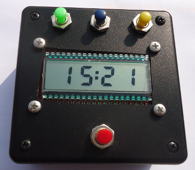
The red button is the start/stop button and the buttons at the top are for setting the count-down time: The blue one enters and leaves time-setting mode, and the green & yellow increment the minute and second value respectively. Minutes roll over to zero after 99 and seconds after 59, and the red button in time-setting mode resets the time to 00:00.
Timing circuitry
The circuitry consist of two circuit boards — for for display and and other for timing control — that are intended to form a sandwich as shown below, and these two boards will be described individually in the sub-sections below. During preperation of the project box a second display PCB was used as a place-holder, which is why the box preperation was not held up while the timing PCB was being fabricated. Both boards were designed using KiCad which these days is my go-to program for PCB design.
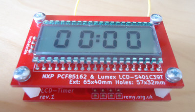
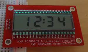
LCD display PCB
The display PCB is the LCD time display I created last April, which in turn was based on an earlier make-shift prototype, and was used because I already had the boards and the required components in stock. It is not exactly cheap since the PCB itself is four-layer for reasons discussed previously and the components themselves — a LumexLCD-S401C39TR LCD display and an NXP PCF85162 LCD driver — have to be ordered in from Digi-Key in the United States, quite likley attracting shipping & import duty costs. Although it does not look as fancy as an LED-based display, it has substantially lower power consumption.
Timing control PCB
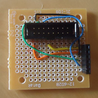
The main circuit board is a PCB version of the perf-board prototype made in Part 1 of this article series, the only notable edition being the two-cell button receptacle mounted on the under-side which was planned for from the start, together with a power switch. The physical dimensions follow that of the display PCB, with identical mounting hole positions and a header intended to connect with that on the display board.
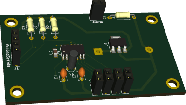
Unusual for my more recent PCBs most of the components are through-hole rather than surface-mount, which is down to space not being at a premium — rather than squeezing the electronics into the smallest space possible, the size of the PCB being dictated by mechanical constraints. Therefore there is no practical motive to use surface-mount equivalents, and particularly in the case of resistors my stock of through-hole components is a lot more extensive than surface-mount components. As for the timing crystal & capacitors I am using a selection of components I have prior experience with and know to work well.
Firmware flashing interface
For flashing the microcontroller on the control circuit board, rather than having a programming header the intention is to use a test clip, as this is logistically simpler as well as allowing a low-profile SOIC chip rather than a DIP chip. The clip connection is shown below — the distance between the micro-controller and the timing crystal is to allow the clip to be put into place, and I got the amount of space just about right. In order to use the programming clip I had to put together an adapter that converts between the 16-pin IDC connector attached to the clip and the 6-pin interface used by the PIC-Kit connection, which is also shown below.
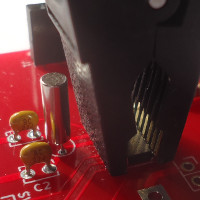
I found that I was having to connect and remove the clip a lot before getting a connection from the flashing software, and in the end I tracked this down to poor electrical contact between the pins and the clip — either an uneven distribution of solder or a build-up of solder oxides over the pins. I used a flux pen to put down some flux and then remelted the solder while observing via a microscope, and the resulting solder joints were much smoother and had a better-looking colour. Once this was done I had no problems getting a good electrical contact and hence a programming connection.
PCB rework
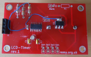
Mistakes with PCB design do sometimes slip in, and the control curcuit in this project is one of those cases — the power supply pins were the wrong way round, which is a screw-up I have made before. This was sorted by cutting power tracks to the chip and then soldering in patch wires to supply the chip from elsewhere — I used the bypass capacitor as the contact point as it would not interefere with connecting a programming clip to the microcontroller. The reworked circuit is shown below.
The root-cause was that the wrong power symbols, as shown below, were attached to each of the pins. This might have been because of a cognitive bias for ground to go downwards and power to go upwards, but looking back at the schematic this was a mistake in obviously plain sight. Although non-critical I felt that the SOIC landing pads were also that bit too small for hand soldering.
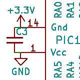
I am not sure how to guard against such mistakes — KiCad can detect against tracks crossing which is why I finally stopped using Fritzing, but the above was a schematic error which I don't think can be avoided via automated checks. I'm sure such mistakes hapen all the time in industry, but in that case there are others doing peer review that would catch non-subtle ones such as this.
Enclosure assembly
The difficult part of modding an off-the-shelf enclosure was done previousy and was covered in Part 2, and as a result the wiring up of the PCBs and the installation into the case went surprisngly quickly. The first thing I did was solder in the power switch connection, though in hindsight I think for this particular connection it would have been better to use something that could be disconnected.
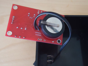
The next stage was wiring up all the control buttons. For expedience I decided to have a common ground — the black wire — rather than connect each button ground individually. To help keep track of which wire goes where, the non-ground wire for each button is the same colour as the button itself, although it did mean using solid-core wires instead of the more flexible multi-strand wires which are better suited for this situation. In the image below the display PCB is also bolted into place.
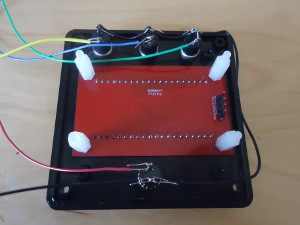
The other end of the wires then need to be soldered to the appropriate place on the control PCB, and once this is done the PCB is bolted into place as shown in the image below. The wires are a lot longer than they need to be, but it would have been a lot harder to solder short wires with the control board already bolted into place.
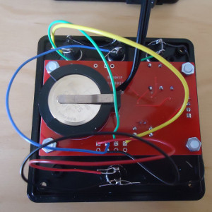
At this point all that is left to do is put the two part of the enclosure together and screw the lid closed. Rather than threaded holes the case comes with self-tapping screws, or at least screws I assume are supposed to be self-tapping.