LCD Timer, Part 1
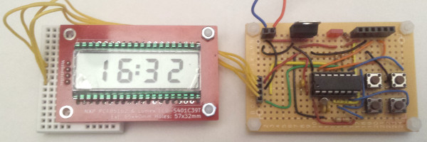
10 February 2019This project is a remake of my count-down timer that uses my LCD-based time display rather than LED chips. It was a project I put off for a long time since in terms of electronics it would not involve very much work, with the vast majority of the effort being in changes to the firmware to support the different display driver. However my LED-based timer had quite poor battery life — with a decent-quality 9-volt power cell I got about six or so months use out of it, but cheap power cells barely lasted one month — so I thought it time to finally build an LCD-based version. This article will cover building of a perf-board prototype and developing of the timer firmware for it. Follow-up articles will cover the building of PCBs for mounting inside a case, since it is about time I did a project involving a bit of mechanical work
Design
Since the time display is on a separate PCB which for this project is self-contained, the circuit is actually quite straight-forward and is summarised in the schematic below; an external crystal for timing and the four input buttons, and a data connection to the display. This lack of complexity is why it has been so long before I did this project — compared to the wiring up of LEDs or the LCD panel, it is a trivial reheat of an existing design of mine. There are some interesting implementation decisions which are covered below.

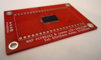
LCD time display
The LCD time display PCB was designed to package up all the complexity of the LCD wiring into a daughter-board, and it involved quite a few tricky design decisions. The first was to have the pin-to-segment mapping follow that suggested in thePCF85162 data-sheet, something that as it turned out required using a four-layer PCB, and even then fanning out all the driver pins and routing the tracks to the LCD pins was a challenge. In hindsight I have no regrets about doing this, as using expedient non-standard wiring for LED displays has come back to haunt me in the past. I also took the decision to hard-wire all the I2C address pins to zero for the address 0x70 because track routing was a challenge as-is without worrying about the three address pins, although this assumed that the LCD display would not be on an I2C bus with other slave devices.
PIC16F1823 microcontroller
For all the previous timing circuits I used thePIC12F1822 for the timing itself, and in order to use much the same firmware & circuit design I will use the PIC16F1823, which is the PIC12F1822 with a few extra pins. This allows me to use the same external crystal wiring I used for the previous LED-based timers — an oscillator setup I know to work and be accurate — whereas the extra pins allow for more buttons to be used. There are also built-in weak pull-up resistors on all pins that can selectively be disabled, which negates the need for external resisitors to avoid floating button states, although it means button input being active-low rather than my favoured active-high.
In-circuit programming
Having solved the problems I was having with in-circuit programming headers, and then remembering how much of a pain swapping chips between the 17-segment LED mainboard and a programming seat, I am disinclined to even consider the latter if I can avoid it. With this circuit it accounts for a significant portion of the total circuit construction effort, but I now don't question its value. The only irritation is that some circuits, and this circuit is one of them, do not operate properly if the programmer is left connected and powered up.External timing circuit
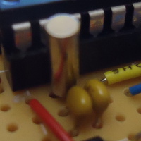
Although I never tried quantifying the error margins my overall experience with the internal PIC clocks is that they are inadequate for timing applications, so an external oscillator is required in these situations. Without a real understanding of the background and no access to test equipment I settled on using an AbraconAB38T 32.768kHz crystal with two 22pF capacitors, which is the setup shown in the image below — it allows for 1.5pF of stray capacitance which I can only assume is realistic because so far I have got good results from the setup.
Power supply
I normally use 5 volts for my circuits, but in the longer term I plan to supply this circuit using button power cells which are 3 volts each, so a two-cell holder — a Keystone 1025 (Farnell 3029815) shown below — will supply 6 volts to the voltage regulator input. A 6-volt input to a regulator that outputs 5 volts is marginal at best as most 5-volt regulators specify an input of at least 7 volts, and theLM7805CT I have normally used in the past specifies 10 volts although I routinely used 9-volt batteries with them. In contrast a 3.3 volt regulator with a drop-out voltage of 1-2 volts needs a supply of 4.3-5.3 volts, which is comfortably below the 6 volts that two button power cells are expected to supply.

The two chips used by this circuit — the PIC16F1823 microcontroller and the PCF85162 driver for the LCD display — are both happy running with either voltage, although flashing a firmware to the microcontroller still requires 5 volts. This is not an issue as the circuit can be powered through the flashing header as well as via the built-in power regulator.
Firmware design
In terms of architecture the firmware is much the same as the time-keeping firmware used for the LED-based timer: A state machine that uses Timer1 with an external crystal and updates a display via I2C. However rather than re-using the previous C-based firmware I decided to write a new firmware in assembly. This is due to doubts about accuracy of timing given how many instructions C code tends to compile to, as well as a general feeling that PIC chips are simply an outright bad target for C code. This is not the first PIC microcontroller firmware I have written entirely in assembly, but it is the first that I have made publicly available in its entireity.Button controls
The LED-based timer had only two buttons: select and action — the select button switched between three states: count-down, increment-minute, and increment-second; the action button acted as a start/stop button for each state. The original idea was to extend this so that the minute & second adjust states had buttons for both increment and decrement, but instead a single time-adjust was used where seperate buttons for incrementing the minute and second digits. The start button was used to add in a reset to00:00 function while in the time-adjust state. At time of writing I was thinking of allowing the minute & second increment buttons to be used at any time, and if I do opt for this it will be reflected in the Bitbucket repository.
Countdown interrupts vs. polling
A source of inaccuracy in overall timing is the delay between the crystal-driven Timer1 timeout and the setting-up of the next timeout, which with the previous LED-based was compensated for by adjusting the count-down timeout by trial-end-error. In this new firmware the countdown code-path is a potential 72 cycles which at a clock speed of 2MHz would take 144μs — for the maximum99:59 timing duration which is 6,000 seconds (i.e. tics) this is a worst-case error of 864ms. In this case I think a maximum cumilative error below the resolution of the display is acceptable. Even this error could be eliminated by using an interrupt handler as upon timeout the handler starts within a small and predictable number of instruction cycles, but on the whole I prefer to use polling rather than interrupts in firmware. Since a microcontroller spends all its time waiting for events and an interrupt handler would in any case need to do polling to find out what event caused the interrupt, it is just easier to simply do the polling in the main execution path.
Clock speed
I tend to use 4MHz as a PIC microcontroller clock speed because it results in a 1μS instruction execution time, but given the low-power nature of this circuit and the actual timing being independent of the clock speed I looked into whether the microcontroller could be clocked lower, even though I am uncertain whether under-clocking a PIC microcontroller actually saves much power in practice. The limiting factor was the clock speed needed for I2C, and from my calculations a clock speed of 2MHz with a clock divider value of four was the lowest that would accurately support the bare-minimum 100kHz BAUD rate, so 2MHz is what I went with.Writing in assembly
When it comes to writing PIC assembly it is great when you are dealing with individual bits, be it input/output values or individual flags within registers, and for the type of predictable bit-banging that PIC microcontrollers are commonly be used for this is perfect. However when it comes to higher-order logic and dealing with variables PIC assembly soon becomes a right pain — and it requiers a very different way of thinking compared to general-purpose programming. There are various ways of coping with all this, which is covered in the following sub-sections.State-machine design
The difficulty of programming if-then-else in PIC assembly, particularly as the only conditional execution is whether a single instruction is skipped or run, makes it preferable to flatten out the code for each state and sub-state. This involves thinking in a very different way to general-purpose (i.e. desktop) programming, which takes a while to adapt to — comparei2cWaitIdle with the C based equivilent. In the process it will quite likley involve things that would otherwise be considered bad software engineering, which highlghts why firmware programming is a distinct skill.
Use of macros
I only found out by accident that gpasm supports macros, and they are a major thing that makes assembly programming significantly more bearable. With instruction sets like that on PIC chips just about every basic operation requires multiple instructions, and it is a headache to manually type them all out while also trying to think about overall program algorithm. A large portion of the main processing loop in the timer firmware involves changing program state and startimg a new loop iteration depending on whether certain button are pressed or not, so it is useful to wrap this up all in a macro:goStateIfBtn macro bit,target local skip ; Makes skip local to the macro BTFSS buttonNow,bit GOTO skip BCF buttonNow,bit MOVLW target MOVWF stateTimer GOTO main skip endm
The macro in this case allows, for instance, the logic for the idle state to be reduced to four lines within the assembly code:
procIdle CALL lcdClearBlink goStateIfBtn 0,0x80 goStateIfBtn 1,0x01 GOTO main
I can foresee myself at some point in the future developing a collection of generic macros, especially for arithmatic operations.
Relative branches
The normal way to use goto branches in assembly is to use a label, but these typically reside in a global name-space, leading to problems with what to call them — this leads to labels such asprocFoo_State that end up being quite long-winded. It is possible to specify relative jumps using the $+x syntax as shown below:. However it is a double-edged sword as it is so easy for the jump distace to be wrong, especially when adding or removing instructions:
BTFSS PIR1,0 ; Check timer GOTO $+4 ; No timeout CALL procTic CALL lcdUpdate GOTO main ; Destination of $+4
Comparison operations
Comparison operations are a real pain, as they involve doing a calculation and then looking at the status bits to see if the result was zero or whether any bits were carried or borrowed. This also potwntially means shunting around values depending on the exact comparison wanted. For instance compare:MOVLW 100 SUBWF value,0 BTFSS STATUS,0 ; W > f (100 > value)
with:
MOVFW value SUBLW 100 BTFSS STATUS,0 ; W > k (value > 100)
Swapping around parameters can be a pain and is a candidate for use of macros. Doing a subtraction then checking the zero flag is how checks for a specific value are done, which is why the firmware instead uses individual bits within the timerState variable rather than its overall value to indicate specific states. The one exception to the awkwardness is checking for zero:
MOVF value,1 BTFSC STATUS,0 ; Is zero
Function parameters
Lastly one of the nicest comparions with PIC programming in C — cheap function calls with parameters. Or rather a parameter, which in practice is all that is really needed in a surprising number of cases. In C there is no access to theW register so any function parameters have to be passed in global variables, but in assembly passing a parameter forward and back is dirt cheap.
The one big bug
In developing the firmware there was only one bug that proved hard to track and fix, and that was alarm state never being entered when the timer expired. Instead it was jumping straight to the idle state rather than waiting for a button press. Within theprocTic routine — shown below — checks for zero are done by looking at the carry/borrow bit after the respective decrements using SUBWF. However when time is up, which is when procTicOver is reached, the minute and second counters would both have wrapped around to 255 due to the decrements and these left-overs from the calculations were not being cleared. These values would end up getting passed to lcdGetSegments resulting in the PIC assembly equivilent of an array overrun by the BRW instruction. Execution was jumping somewhere — probably the time-adjustment routines — that was then falling back to the idle state.
procTic CALL setTicTimer ; Process seconds MOVLW 1 SUBWF timeSecs,1 BTFSC STATUS,0 ; Jump if there was borrow RETURN ; No seconds left. Look at minutes MOVLW 1 SUBWF timeMins,1 BTFSS STATUS,0 ; Jump if there was borrow GOTO procTicOver ; Still time left. MOVLW 59 MOVWF timeSecs RETURN procTicOver BSF PORTA,2 ; Light alarm LED MOVLW 0x04 MOVWF stateTimer RETURN
The underlying issue is how much care needs to be taken to clean up state after coincidental calculations, in this case the in-place subtraction that is written back before the zero check. Mercifully with the PIC16F1823 96 of the 128 bytes of data memory and the vast majority of the registers required for this firmware are on Bank 0, so any functions that need to switch to other banks — just I2C stuff in this case — do a switch back to Bank 0 as a routine part of pre-return cleanup. However it is all to easy to miss a bit of cleanup, and this adds to the debugging effort.