Bootstrap ARM Cortex-M4 PCB
19 September 2018Following on from successfully bootstrapping an ARM Cortex-M0 I wanted to try out an an ARM processor that had significantly more storage — both program and memory — and eventually I settled on the ST-Microelectronics
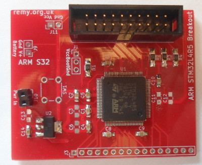
STM32L4R5 Cortex-M4 (Farnell 2851038) which had 640kB RAM and 2MB program flash. This chip is a 100-pin LQFP which has pins on four sides, and realistically I knew this meant making a prototype PCB to host it — I did find a 100-LQFP to DIP adapter (Farnell 2474701) but it cost almost as much as the chip itself, and Seeedstudio at the time were doing a special offer on 3-board PCBs for $4.90.
As with the Cortex-M0 article that targeted an NXP LPC1112FD20, the Olimex ARM-USB-TINY-H will be used for programming/debugging, so only the Cortex-M4 details will be covered. Full JTAG rather than a SWD (serial wire debugging) connection will be used, even though both are supported by the chip, which negates the need for the ARM-JTAG-SWD adapter.
Circuit design
The circuit is based on the reference design given in the Getting Started document (AN4555 for the processor, the main feature of which is a 0.1μF decoupling capacitor on each of the four power connections. Some of the other pins required capacitor pairs, although I did not solder in many of then, as a had a hunch that they were not strictly required. I also included other things from the reference design such as the reset button circuit, but deviated in other things such as keeping the battery power pin separate from the main power supply. For simplicity and convenience the circuit includes its own voltage regulator, since the STM32L4R5 requires 3.3 volts rather than the 5 volts I typically use.
Hardware connections
I had originally wanted to fan out all 161 of the GPIO ports, making use of compact “Micro-MaTch” connectors (Farnell 2473354), but due to logistical complications ended up just fanning out the pins for a single 32-bit port. I included a power take-off for external circuits since 3.3 volts is not my usual circuit voltage, and the on-board power regulator is capable of supplying 500mA. Although theSTM32L4R5 supported both JTAG and SWD, I opted for the former using the same size of connector as the Olimex programmer/debugger for simplicity, and used the standard JTAG pin-out.
Design flaws
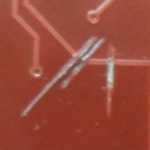
When checking the output voltage of the external power interface I noticed an unusual voltage drop, and that the voltage regulator was getting suspiciously hot. As it turned out the two power rails seemed to be shorted, which by comparing a PCB that included just the processor with one that was bare, tracked down to the processor itself. The chip includes two holes that could be interpreted as Pin-1 indicators, but in the end I tracked down the short: Swapped power pins. The data-sheet usesVdd and Vss, whereas my own circuit nomenclature is Vcc and Gnd, and two of the four power pin pairs were swapped. Thankfully it looked like the power pins are internally connected, so I was able to cut the tracks of the two power pairs that were swapped, and after this the circuit seemed to be fine.
Cutting PCB tracks rather surprisingly requires only a stroke or two with a Stanley knife, but all four incorrect tracks needed to be cut before checks with a multi-meter showed that the short had been removed.
Mercifully the tracks needing to be cut were in relatively sparse areas. Only using two of the power connectors might cause problems down the line, but it will probably be fine for just running firmware with minimal loads on the GPIO pins.
Connecting to the ARM Cortex
It is assumed that OpenOCD has been built and will be used to control the Olimex programmer/debugger that will connect to theSTM32L4R5. The following command will establish the connection:
BASE=/opt/openocd/v0.10.0; ${BASE}/bin/openocd \ -f ${BASE}/share/openocd/scripts/interface/ftdi/olimex-arm-usb-tiny-h.cfg \ -f ${BASE}/share/openocd/scripts/target/stm32l4x.cfg
Note the absence of the olimex-arm-jtag-swd.cfg line compared to the command-line for flashing the NXP processor. If successful, you should see the following output:
Info : auto-selecting first available session transport "jtag". To override use 'transport select <transport>'. adapter speed: 500 kHz adapter_nsrst_delay: 100 jtag_ntrst_delay: 100 none separate cortex_m reset_config sysresetreq Info : clock speed 500 kHz Info : JTAG tap: stm32l4x.cpu tap/device found: 0x4ba00477 (mfg: 0x23b (ARM Ltd.), part: 0xba00, ver: 0x4) Info : JTAG tap: stm32l4x.bs tap/device found: 0x06470041 (mfg: 0x020 (STMicroelectronics), part: 0x6470, ver: 0x0) Info : stm32l4x.cpu: hardware has 6 breakpoints, 4 watchpoints
The final line about breakpoints and watchpoints is the giveaway that the connection is successful.
Remarks
If it was not for the swapped power pins this PCB would have been practically perfect — the design had no other issues, it seems to work as intended, and one of the two hot-plate reflow solderings I did had no solder bridges at all. The latter is a big thing considering that, as with my first experience with TSSOP, it was my first experience with a yet-even-denser chip form factor: 100-pin LQFP. It will be some time before I will be writing firmware for this chip, as I intend to use the NXPLPC1112FD20 Cortex-M0 as the base for my near-future experimentation with ARM rather than the STM32L4R5 Cortex-M4, but knowing I have hardware ready to use is a great confidence boost.