LCD Timer, Part 2
24 February 2019In a previous article the design and build of a prototype LCD-based timer was presented, with the ultimate aim of making a PCB version that would be mounted inside a project box. Preperation of the project box is the subject of this article, with the final assembly of the complete timer being the subject of a future article — at time of writing the PCB version of the timer circuit is on order, but its absence does not block this stage of the whole project.
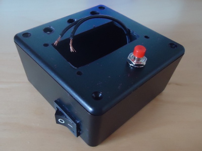
In the past Maplin had a good selection of project boxes, but Maplin is now long-gone and I have had mixed experiences with boxes from various sources. The box I used for the PIC16F88 Timer PCB was good but including shipping they were £4-5 each which is a bit steep. However all the cheap boxes I have come across tended to be that bit too small for my purposes and of dubious build quality — they needed what I consider an excessive amount of force to get lids in place. After much searching I found the Takachi TW8-4-8B (Farnell 2444694) which I felt was a good size, and for the quality a good price.
The display slot
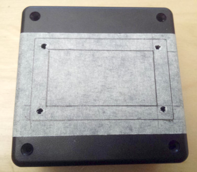
The display slot is to be cut into the lid of the box, and due to its visibility is the most critical part of the whole project box preperation process. The first thing to get right is the position of the bolt holes, and I used standoffs sandwiched between two boards because it provides a reference that is a lot more rigid than a single board — a single board allows bolts to be at an angle and I found that the resulting looser tolerance causes problems down the line. I used a hand drill for these holes because the drill bit can be put directly through the PCB holes without a big risk of excess speed wrecking the PCB. At this stage a tight fit is desirable as drawing around the edge provides the best references for a cutting template, as shown below:
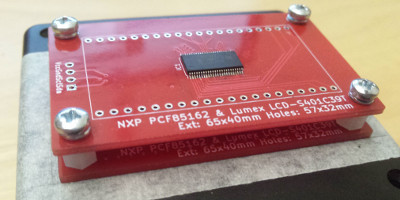
With holes in place and an outline drawn around the circuit board while it is in place as shown above, it is now possible to draw out an accurate template for use as a cutting reference, as shown below. With holes in place and an outline drawn around the circuit board while it is in place as shown above, it is now possible to draw out an accurate template for use as a cutting reference, as shown below. First time round I tried drawing out the whole template before I started drilling, but this ran into trouble as it turned out to be relatively difficult to drill holes accurately.
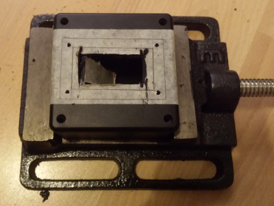
Last year I invested in a Dremel 300 but I suspect that the cutting disc it is equipped with is unsuitable for cutting plastic — it looks like it is really intended for use with metal, and has a tendency to cause some of the plastic to melt. Using a small heavy vice to hold the box in place it makes quite a rough cut, and quite a mess, as shown below. This is one part of the process when you really need to wear safety glasses as bits of plastic well be thrown in random directions. In the future I might look into alternative cutting discs such as the SC476 but in this case a rough cut is all that is needed at this stage.
For a close-fitting slot I find the best thing is to use next is a nibbler, which as its name suggests takes a small ite out of the plastic. The idea is to gradually widen the gap as shown below. The one disadvantage is that the nibbler I used is intended for slightly thinner material, so a bit of force is needed to get the nibbler in place for each “bite” which can make the process hard on the hands. It can also be tricky keeping the edge straight rather than a bite going that bit too far.
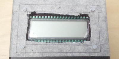
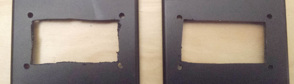
Once the LCD display fits — or is close to fitting — all that is left is to finish off the edge with a file. As is typical with craft-work what works well for one person might be a pain for another, and it is quite likley it won’t be quite right first time, but with each iteration you gain that little bit of experience. Below is shown my first and second attempts at cutting the LCD slot:
Adding the power switch
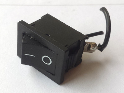
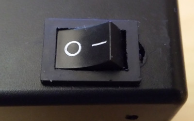
The power switch I used is one I scavenged from a load of electrical equipment I was about to take to the local waste disposal site because it was in front of me and felt it was the kind of switch I wanted to use for this project. The switch is shown below in its just-scavenged form — had I not decided to cut it out of the thing I was about to dispose of, I have no idea it would take to find something like it from my usual vendors, and that is before thinking about price.
For this switch the method I used was cutting the case by drilling and then reaming a hole big enough to get a nibbler in place — for expedience I drilled two holes next to each other and joined them together. Once the hole was big enough to get a nibbler in place it was a case of taking bits out of the case until the hole was the right size for the switch, as shown below.
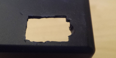
The nibbling is a bit on the rough side but unlike with the display slot these edges will not be visible. The hole was slightly too big so I needed a small spot of superglue to keep the switch in place rather than relying on the grips on the switch itself, but on the whole I am happy wth the results.
Putting in the control buttons
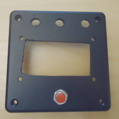
Compared to cutting the display slot and to a lesser extent cutting the switch slot, adding the control buttons is relatively easy — a case of drilling holes in the requires place and using a reamer to expand the holes until they are wide enough the accomodate the buttons. In the image below the bottom red start/stop button is shown in place, whereas the other three fully-reamed button holes are shown unoccupied. I think it would have been a lot easier to drill a small pilot hole and then use a 5mm drill bit rather than a hand reamer to enlarge the hole to the required size — the edges of the hole will be covered by the retaining nut, so there is some tolerance to how big the hole can be.
The next stage
The box itself is complete, so all that is left to do is build and install the circuitry for the timer and display — the PCB for the display was made last year but the PCB for the timing circuit has yet to arrive from the fabrication service in Shenzhen, so circuit-related discussion and its installation will be covered in a future article. Becaue the two PCBs were intentionally designed to be the same physical size, the timing PCB was not required for the box production process.This part of the project utilised the experience gained from creating the box for my previous LED-based timer, with most of the work being done using a nibbling tool — a major annoyance is that the thickness of the plastic is at the limit of what the nibbler can handle, which is due to the nibbler really being intended for sheet metal rather than plastic. I learned that a large file should be used for finishing, although I slightly overdid it for the display slot on the cover. All I really need is more experience, since I have all the tools required for the task of preperaing project boxes.