TCA9535 expander breakout
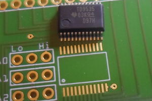
06 January 2018Although I have already done surface-mount reflow PCBs, here I am extending that experience to SMD integrated circuits rather than just discrete components. In this case I opted for the SSOP form factor of the TI
TCA9535DBR 16-bit I/O expander (Farnell 2627594; data-sheet) as it was a chip in which the data-sheet landing area specification and that within Fitzing seemed to match up. The scale was also smaller than that I encountered within my Darlington board, which was an intentional added challenge.
The TI TCA9535DBR, like the PCF8574, is an open-drain chip where output pins act as current sinks. Although more sophisticated than the PCF8574, it is nowhere near as feature-laden as the MCP23017, and personally I prefer the somewhat restrained nature of the Texas Instruments expanders I have used so far.
The silicon
I decided to forego getting a solder stecil with this order, as the cost of the stencil was almost as much as the three PCBs themselves, and in any case I wanted to do things manually this time round. I reflowed two breakout boards, partly in the mistaken belief that I had partly burned out the chip in the first attempt. The first had used which resulted in somewhat mammoth solder bridges, but for the second attempt even what I thought was a conservative amount also produced a lot of bridging:
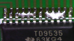
The guide I was using suggested putting down flux, heating up the bridge, and then just sweep it away. Some solder bridges actually magically vanished upon doing this, but most didn't — I suspect a large part of the problem is that my soldering station tip is both too large and the wrong shape for de-bridging chips of this size. Maybe I also used a bit too much flux, or the tip was not quite clean enough. Either way it took longer than it should have, and was a bit of an ordeal.
I had thought about doing a manual soldering of the third and final PCB using my soldering station, but the soldering tip I have is far too big for the task, and with the short-circuit with the address lines the remaining expander chip is more valuable being kept in reserve. This is a technique I intend to try out, but am going to hold back because this size of components is that bit too unforgiving.
SOIC vs SSOP
I had wanted to use the slightly larger SOIC form-factor, mainly due to it having gaps between pins that are a lot wider than the widths of the pins, and in hindsight I suspect this would have made solder bridging & their removal that bit less of a headache. However when comparing various data-sheet recommended landing patterns with the pad layouts in Fritzing, 24-pin SSOP was the first that seemed to actually match up. While having a reasonably good selection of discrete SMD component pads, its selection of SMD chip mounting is somewhat sparse, and I have little faith in them being the right size. All too often I change the number of pins and Fritzing selects a supposedly similar form-factor, and an actual motive of this project was verifying that the chip actually fitted. I plan to give alternative PCB programs a go in order to try out SOIC chips, as SSOP is that that bit too small for my liking.Design flaws
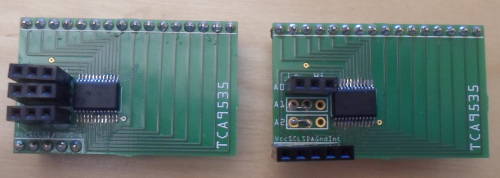
Unfortunately, a design fault slipped into the PCB. Because the track from the expander's interrupt pin to the external interrupt connection is on the wrong side of the PCB, it short-circuits the A1 & A2 address pins. The workaround I used was to permanently fix A1 & A2 to ground — since the interrupt pin is open-drain which acts as a current sunk when active, tying it to ground won't cause any serious problems, unlike tying it to Vcc which would cause a huge current draw should an interrupt be asserted. As a result there is only a choice of two I2C addresses and interrupts cannot be used, but given my likley use-cases these are acceptable limitations.
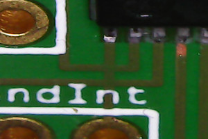
Nevertheless it is embarrassing. I think other PCB tools would at least detect crossed tracks, but Fritzing does not seem to have any actual safety mechanism. Had just about any other combination of tracks been crossed, and the whole PCB would probably be bricked. I might just about be able to cut the interrupt track, but given the size I doubt I will be able to add in a bypass patch wire.
Expander usage
While notionally a 16-bit expander, the input/output pins are presented as a pair of 8-bit ports, which seems to be the usual abstraction. TheTCA9535DBR is register-orientated in that all read & writes need to include an internal register address, which the data-sheet terms the command byte. For demonstration purposes I will use my usual Python TxRx script coupled with the USB-ISS, the scemantics of which are detailed elsewhere. Firstly the command to setup the USB adapter needs to be sent, and in this case will use 0x70 for 400kHz I2C, since that is what the expander is capable of:
./ttyTxRx.py /dev/ttyACM0 2 5a 02 70
I will assume that all the address pins are tied to ground, resulting in a I2C device address of 0x40.
Port configuration
This register controls which pins are input an which are output, and by default all pins are input. Port 0 uses0x06 and port 1 uses 0x07, so the following sets all of Port 0 to input and all of port 1 to output:
./ttyTxRx.py /dev/ttyACM0 1 55 40 06 1 ff ./ttyTxRx.py /dev/ttyACM0 1 55 40 07 1 0
Port reads
Unlike the other registers, this one is read-only, and reading from it reveals the current state of the physical pins. Port 0 uses0x00 and port 1 uses 0x00, so reading from both ports in turn can be done using the following:
./ttyTxRx.py /dev/ttyACM0 1 55 41 00 1 ./ttyTxRx.py /dev/ttyACM0 1 55 41 01 1
One thing to keep in mind is that this particular expander is somewhat unforgiving with floating input pins, to the extent that it can easily be mistaken for either a faulty chip or short-circuits — expect odd results if any pins don't have pull-up or pull-down resistors.
Port polarity
Port polarity allows the values being read from input pins to be individually inverted, so upon a read operation the returned byte is XOR'd with the values in this register. Port 0 uses0x04 and port 1 uses 0x05, and for me setting all 16 pins to the default non-inverting is preferred:
./ttyTxRx.py /dev/ttyACM0 1 55 40 04 1 0 ./ttyTxRx.py /dev/ttyACM0 1 55 40 05 1 0
Port writes
Port writes are actually writes to the output latches, which in turn can also be read, although I have never really regarded the ability to do the latter as having much practical use. Port 0 uses0x02 and port 1 uses 0x03, so setting all output pins to “on” can be done using the following:
./ttyTxRx.py /dev/ttyACM0 1 55 40 02 1 00 ./ttyTxRx.py /dev/ttyACM0 1 55 40 03 1 00
Keep in mind that since the outputs are active-low open-drain, a cleared bit is “on” (i.e. pin grounded) and a set bit is “off” (i.e. floating), so you will have to mentally invert your thinking when testing with an array of LEDs.
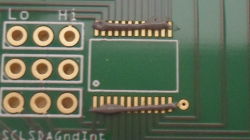
Address pins
Like most devices, three of the device's I2C address bits are set via external pins, and the read & write addresses from different combinations of pull-up& pull-down are shown in the table below. This is basically Table 2 on page 22 of the data-sheet normalised to the byte view of I2C addresses I prefer:
| Address pins | I2C address | |||
| A2 | A1 | A0 | Write | Read |
| Lo | Lo | Lo | 0x40 | 0x41 |
| Lo | Lo | Hi | 0x42 | 0x43 |
| Lo | Hi | Lo | 0x44 | 0x45 |
| Lo | Hi | Hi | 0x46 | 0x47 |
| Hi | Lo | Lo | 0x48 | 0x49 |
| Hi | Lo | Hi | 0x4a | 0x4b |
| Hi | Hi | Lo | 0x4c | 0x4d |
| Hi | Hi | Hi | 0x4e | 0x4f |