LCD timer enclosure
07 March 2021This is a much-delayed follow-up to the second-generation LCD timer that was finally realised last summer, and this in turn was part of a much larger stop-start project that began around mid-2019 and had originally hoped to complete before I went to Korea that Christmas. My previous timers were ones that I often used in preference to one on my mobile and as a personal treat I decided to finally get round to finishing this one off.
Choosing the box
Many of the details are lost to the mists of time but at some point I ordered in both the Hammond Engineering1591XXSS and 1591XXLS enclosures, and ended up designing the PCB for the wrong one.
Originally I hoped to have a single-board design but it was pretty clear that the 1591 SSL enclosure was too small, so I went ahead with having separate schematics for the two boards and seeing how the LCD panel would fit between the mounting holes.
However I then found the 1591 XXS I had also ordered and almost immediately reverted back to my plan for a single board.
In hindsight the switching between single-PCB and dual-PCB designs I suspect was at least indirectly responsible for some of the flaws the first revision of the circuit board had.
From the start this would be a project with complications.
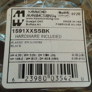
Finding decent boxes that are also a good price is not easy and often as not when such ones come along the price soon gets jacked up — the sample 1591XXSS I ordered in 2019 was €2.53 but this was increased to €5.65 not that long afterwards.
Back when Maplin still existed project boxes were often around the £5 mark but you could at least see what you were getting.
It is possible to get cheaper boxes off E-Bay but I have generally found them disappointing — then again at least it is not too bad to waste a few while figuring out the best techniques for making the customisations.
Enclosure customisation
It is not often I have an excuse to do some craftwork, and being mid-pandemic the opportunities have become very rare, so this was something I decided to do while I had access to all my tools and the space to do it. The tools I have are pretty much the right ones for the task but I feel that my technique needs more practice. Using a box that already had mounting studs helped a lot as getting the bolt holes right was a major headache with the previous timer enclosure.The display slot
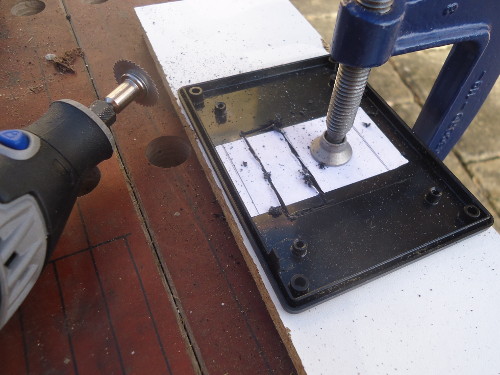
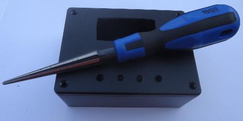
The major part of the box preparation is cutting the slot for the LCD panel. The Dremel blade I used previously for the rough-cut was intended for metal, so when used on plastic the resulting friction tended to melt the plastic rather than cut it away. This time round I used a blade intended for cutting wood, which did a much better job as it works by chipping the plastic away. There were some issues with the lid being clamped directly to a board so the cutter also cut into the wood as well, but for a right-cut this was not a major problem.
Getting the rough-cut hole into the final shape was done using a file, although I should have used a larger rectangular one rather than the triangular one shows in the picture — for some reason the latter was not packed with the rest of my tools when they were shipper over in December. It is difficult to get exactly right especially since I have not practised since I made the enclosure for my previous timer a touch under two years ago but that said the results are clearly better.
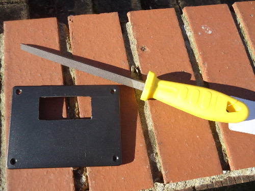
While a Dremel is capable of making a good final cut in one go, in practice a rough-cut followed by finishing off with a file seemed to be the optimal approach given that I was not sure how big the gap needed to be for the display.
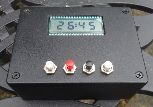
The button holes
I was unsure where to put the buttons or even how many to use, but in the end I decided to use all four and place them all on the lid below the display. As a result they were all placed in a single row although in hindsight I am not sure if this was the best place to put them all even though from the outset that is why I put the notch in the PCB. Since building the previous timer I had purchased an electric drill as I felt that the hand drill I used previously was more trouble than it was worth. Firstly a 2mm drill bit was used to create pilot holes which were then expanded using a 4mm drill bit, and then finally a reamer was used to finish them off.
Ideally I would have made my way up through ever larger drill bits but since I did not have any larger ones in my toolbox I could not do this. I had thought about investing in a “christmas tree” drill bit but I am unsure whether this would be a good option compared to a pack of standard drill bits given the ease of drilling too far.
Power switch
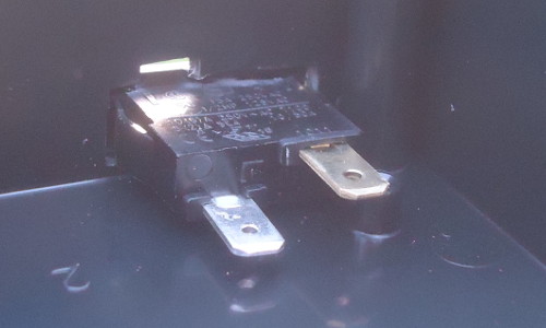
For the switch I drilled a hole that allowed me to insert a nibbler, and then used a nibber to turn the hole into a slot suitable for the power switch. I ended up making the slot that bit too wide, as well as an accidental ‘nibble’ upwards which can be seen in the picture below, so I used some superglue to secure the switch into place. Should have taken a bit more care with the nibbling although I suspect I would have ended up using glue to secure the switch in any case.
Wiring things up
I used some cheap push-buttons ordered off E-Bay because they are one of those things that seem to be easier to find there rather than the likes of Farnell. They arrived earlier than expected so soldering in the connections was a bit of a rush job before I headed to the airport, but on the whole I have no regrets about how things turned out. It could have been prettier but all this stuff is on the inside of the box and will hardly ever be seen, but it meant that I had a working unit before I flew out.
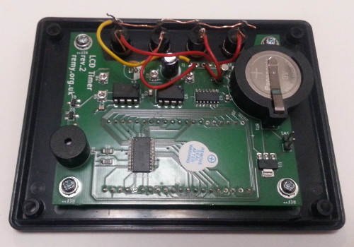
For the power connection I had wanted to use a crimped connector that I could attach to the existing pin header but I did not have any at hand at the time. In hindsight maybe I should have used a pin receptacle rather than soldering wires directly but I did not think of this until I had finished — if I make a second unit this is certainly something I will consider, but with one operational unit I have little motivation to make a second unit.
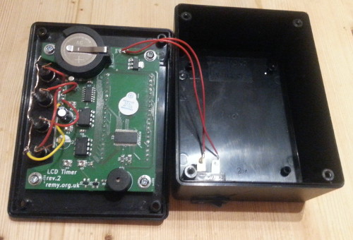
I had some difficulty soldering the wires to the power switch, but this may be down to using lead-free solder with a cheap soldering iron which is often problematic with connectors such as these that can absorb a lot of heat. The switch just happened to be one of three or four that I had in mind and was the only one I had actually got round to buying.