RS232-driven LCD display
01 December 2017Although not quite a clone, this project is basically a reimplementation of an LCD display & input module I used while working in the UK back in 2010-2012, which in turn has been a long-term ambition I had already completed in parts. Since I had all the major circuit components and test equipment in stock, I decided to finally bring this vanity project of five years to a final close. It was also an opportunity to properly try out the
PIC16F88.
The LCD display is controlled via commands sent over an RS232 connection operating at RS232 voltage levels, so this module is basically a display that can be driven from a PC. Button presses are signalled back over the same RS232 connection, but for me this is a relatively minor thing. The only outward functional difference between this and the original module I used back in 2010-2012 is the number of buttons and the size of the display, although I have no idea how the insides compare.
Choice of microcontroller
My previous LCD projects used thePIC16F630, but I wanted to try porting the LCD control code to a different chip, and in any case the PIC16F630 has no hardware support for any serial communications — implementing RS232 in firmware was not something I would do. Although I did have some vague ideas about dual-purposing this project as an I2C-driven LCD display as well as an RS232-driven one, my choice of the PIC16F88 was ultimately down to being the most suitable UART-equipped microcontroller I had in stock — most of the others had insufficient (or far too many) pins or were not supported by gpsim.
At first the different PIC microcontroller seem to be vastly different, which they often are in terms of initial setup, but functionality of modules such as RS232 support is actually much the same — often down to even the bit-structure of control registers. Using a new PIC chip still requires a bit of experimentation, but after trying 3 or 4 different ones you start to notice where the differences tend to be. The PIC16F88 chip was originally my candidate for the single chip I would use for all future project, but its lack of hardware support for I2C master — a non-issue for this particular project — scuppered that intention.
Design
The PIC microcontrollers tend to concentrate pins that are part of the same I/O port towards the ends of the chip rather than along the same side, which in this case worked to my advantage due to the LCD header's location along the side. I used the same prototyping board (Farnell 2768280) I used for my previous LCD timer, which is designed for use with integrated circuits, and the nice thing about it is not having to cut tracks — working out where to drill out tracks and then doing so was particularly time-consumping with previous circuits. It still has some irritations, but on the whole I think it a lot better than my previous strip-board.At the time I designed the circuit I was undecided whether to include pull-down resisitors for the buttons on the circuit itself — partly because I did not know what type of buttons I would eventually get in stock, and partly because keeping the pull-downs off-circuit means the pins could potentially be used for other things such as I2C. For simplicity I left them out of the original design, because I was undecided whether the buttons would be board-mounted or external. I did the board layout in Fritzing, which is shown below (left) alongside a picture of the built hardware (right) for comparison.
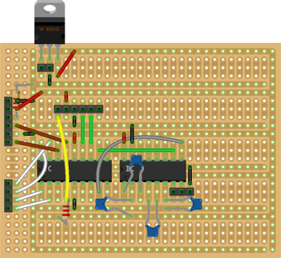
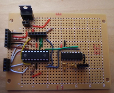
Some minor repositioning is evident, but by and large component connections ended up either in the hole they were intended to go into, or one neighbouring the intended hole. The RS232 driver and the things around it were shifted right a bit, the connections around the voltage regulator were rearranged, and some resisitors were positioned a bit differently, but as a total sum of “significant” changes it does not amount to much. The only post-design addition to the circuit was connecting up the 6th pin of the flashing header, along with a ~20KΩ pull-down resisitor, to Pin 9 of the microcontroller. This notionally enables low-power programming mode, but wired up this way it can also be used for connecting an external button for testing purposes. In the end I decided to use the flashing header to connect all the buttons, because I felt that there was little to gain from having more than three buttons.
Faults & rework
I have generally had relatively good luck with my more recent circuit boards, having not had to do a scrap-and-restart since my LED row driver board, but that does not mean the process of assembling them went entirely smoothly. I have been a lot more blasé compared to say what went into my DEM16217 LCD display, which includes more adventurous reworking. This section covers some of the pit-falls I had with this project, and how I mostly got around them.Miswired Vpp/MCLR pin
I actually noticed this in a visual sanity check long before I powered up the circuit, but the Vpp connection from the chip flashing header was routed to Pin 3 rather than Pin 4— the tightness of the yellow wire around the chip recepticle and the angle of the MCLR pull-up resisitor sort of give away the rework. Probably just as well I caught this one early on, as Vpp voltages are a lot higher than what I think the other pins can tolerate, but it shows how easy it is for a little mistake to slip in.In-circuit flashing problems
I don't really know the details of why, but adding in the RS232 Driver interfered with in-circuit flashing, and simply disconnecting the driver from the Vcc power rail did not solve this problem. My guess is this is to do with capacitance (or much less likley, inductance) on the power rails that is not properly accounted for, but doing so at the moment is beyond my current knowledge of electronic circuits. If I was to redesign the circuit tomorrow, I would probably use the brute-force approch of adding in jumpers to isolate different parts of the circuit.Garbage RS232 output
When I first connected up the circuit to an external RS232 adapter, I basically got garbage output, and spent a while trying things such as different BAUD rates in PuTTY, and even doing a partial rewiring on solderless breadboard. I eventually worked out it was a problem with the RS232 Driver, and in turn found out that the ground pin on the RS232 header (bottom-right, next to the capacitors) was not connected. It was due to a poor solder joint, shown below under magnification:
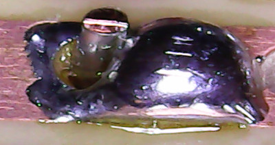
To the best of my knowledge the problem was the wire not getting hot enough, so it ended up surrounded by small insulating layer of flux, rather than the solder bonding with it to create an electrical connection. This seems a particular problem on prototyping board where the copper tracks are just on the surface, in contrast to PCBs where the hole itself is lined with metal all the way through. Poor connections seems to be a more common problems than short-circuits, although both problems can be found by checking pins with a multi-meter in resistance mode.
Inputs not working
This one really caught me as I only tested it at a very late stage — onlyRB7 worked properly when I wired in a load of push-buttons with pull-down resistors. I put this down to damage due to the circuit having a rough time in transit, as although I don't de-bounce the switch inputs, they ought to settle on a value eventually. I decided not to investigate for now, as not having multiple working buttons is not a major issue, particularly as I never got round to finding a suitable case to put the circuit & display into.
Firmware
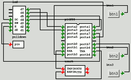
This circuit can be represented entirely within gpsim, as shown in the image below, so development of the firmware itself is independent of the hardware — this suits me fine as it means I can write about the hardware & firmware issues in a compartmentalised way. My interests are much more towards circuitry than firmware, but this project brings together information on various microcontroller functionalities, which previously were split between different articles using different chips.
This section will concentrate on the setup of the various PIC16F88 modules, as longer-term these are of interest rather than the overall purpose of the firmware. To enable this I split up the firmware into functions in a way that would probably not be done with a production product.
Chip clock rate
As a rule-of-thumb, if serial communications are required, then PIC microcontrollers have to be run at or close to their maximum clock frequency. The main advantage of running at lower clock speeds is supposedly lower power consumption, but I don't know any figures to quantify the savings, and in any case power efficency is not normally a major concern of mine. I opted for aFosc of 2MHz as this seemed to be the lowest clock speed that could also sustain 9,600 BAUD RS232 within reasonable error bounds. This clock speed is selected using IRCF=0b101 via the OSCCON register, the details of which are on Page 40 of the data-sheet, and performed by the function below:
void clockSetup(void)
{
OSCCON = 0b01011000;
while( ! (OSCCON & 0b100) );
}
I am not entirely sure how clock switching & stabalisation works, but the checking of the IOFS flag within the OSCCON register is supposed to be done before any timing-critical code, which is something I prefer to get done & dusted as part of start-up code. To my knowledge the code above ought to make sure everything is in the correct state.
Timers
As with my count-down timer, I used the Timer0 functionality, which is basically the same on both the PIC16F630 and the PIC16F88. Although originally intended to be a 1.0-1.5ms delay, testing under simulation revealed it to actually be 1.6ms — I stuck with 1.6ms as my experience so far is that hardware runs faster than the nominal speed, so I saw no point in adjusting the delay.
void timerSetup(void)
{
OPTION_REG = 0b00000111;
}
void lcdDelayMS(void)
{
// 1.6ms
INTCON &= ~0b100000;
TMR0=253;
INTCON &= ~0b100;
INTCON |= 0b100000;
while(!(INTCON & 0b100));
INTCON &= ~0b100000;
}
For shorter delays I simply reused an assembly-language delay loop, adjusted for the different clock rate, for reasons I covered in the article linked to. Simulated in gpsim, using 3 came out at 38ms for the whole function and 4 came out at 46ms. I was going to go with 6 (notionally 62ms) to provide some slack for the hardware, but in the end this was not required, as the HD44780-based devices seem to be forgiving in practice to the delays needed for display updates.
void pinSetup(void)
{
TRISA = 0b00100000;
TRISB = 0b11001111;
ANSEL=0;
INTCON &= ~0b1;
INTCON |= 0b1000;
}
The input/output direction of
if( INTCON & 0b1 )
{
INTCON &= ~0b1;
iButtons = PORTB;
// Other processing
}
Instead of using code like the following to check for pin changes, I resorted to polling the whole of
void rs232Setup(void)
{
TXSTA = 0b00100100;
RCSTA = 0b10010000;
SPBRG = 12;
}
It has to be pointed out that the data-sheet for the
void lcdBangNibble(unsigned char bits)
{
PORTA=0b10000000 | bits;
lcdDelayMS();
PORTA=0b00000000 | bits;
lcdDelayMS();
}
void lcdWrite4(unsigned char letter)
{
unsigned char lo = letter & 0b1111;
unsigned char hi = letter >> 4;
PORTA=0b11000000 | hi;
lcdDelay();
PORTA=0b01000000 | hi;
lcdDelay();
PORTA=0b11000000 | lo;
lcdDelay();
PORTA=0b01000000 | lo;
lcdDelay();
}
Using the above functions, setting up the LCD display can be setup using the same procedure I used in previous articles — the details of the latter are beyond the scope of this article.
void resetWatch(void)
{
__asm CLRWDT __endasm;
}
#define NO_BIT_DEFINES
#include "pic16f88.h"
__code short __at (_CONFIG1) cfg0 =
_FOSC_INTOSCIO & _WDT_OFF & _MCLR_OFF & _PWRTE_OFF & _CP_OFF & _CPD_OFF;
void main(void)
{
unsigned char iByte;
unsigned char iButtons;
unsigned char iPresses;
unsigned char iPrevButtons = 0;
clockSetup();
pinSetup();
rs232Setup();
timerSetup();
lcdSetup();
iPrevButtons = PORTB & 0b11001000;
while(1)
{
iButtons = PORTB & 0b11001000;
if( iButtons != iPrevButtons)
{
iPresses = 0;
iPresses |= (iButtons & 8 ) ? 0b001 : 0;
iPresses |= (iButtons & 64) ? 0b010 : 0;
iPresses |= (iButtons & 128) ? 0b100 : 0;
rs232Write('\r');
rs232Write('B');
rs232Write(':');
rs232Write( '0' + iPresses);
iPrevButtons = iButtons;
}
if( PIR1 & 0b100000 )
{
iByte = RCREG;
PIR1 &= ~0b100000;
if( iByte == '\r' )
{
lcdBangNibble(0b0000);
lcdBangNibble(0b0010);
continue;
}
if( iByte == '$' )
{
lcdBangNibble(0b0000);
lcdBangNibble(0b0001);
continue;
}
lcdWrite4(iByte);
}
resetWatch();
}
}
Although my memories are are little hazy, my overall recollection is that this module is substantially more responsive than the one I used in my previous company — I suspect this is down to actually knowing what the underlying latencies are actually caused by, and making a protocol that exposes more of how the LCD panel is operated electronically.
Pin setup
This function sets whether the various pins are input or output — the mnemonic TRIS refers to the tri-state mode the pins use, as input pins typically use high-impedence. The pins are also all set to be digital I/O rather than using any analogue functionality, and interrupts are enabled for pin state changes on Port B.
RB2 & RB5 are actually overridden when the USART is enabled, but for consistency I prefer to set the direction of those pins to what they are expected to be. For the PIC16F88 interrupt-on-change is only for the PORTB pins on the higher-numbered side of the chip, and the set of pins included in interrupt-on-change is fixed. This is a bit of a let-down given that the PIC16F630 via the IOCA register has full-flexibility of which pins can drive an interrupt, and it means pin state change cannot use the following for the pins I am interested in:
PORTB constantly, and reacting if the polled state differed from the polled state.
RS232 BAUD
One thing I did not quite get the hang of last time I looked at RS232 BAUD rates was the purpose of the BRGH flag, which dictates whether the clock speed is divided by 16 or 64 within the USART module. Here I will set the flag to get division-by-16, which allows 9,600 BAUD to be supported at a clock speed of 2MHz. For a 2MHz clock, the SPBRG value of 12, which is obtained from Table 11-6 (Page 101) of the data-sheet.
PIC12F88 gives a selection of pre-calculated SPBRG values, whereas that for the PIC12F1822 used in the I2C-RS232 bridge only gave a single worked-out value — 9,600 BAUD at 16MHz clock speed. This is partly responsible for my incorrect belief that PIC chips could not support higher BAUD rates.
LCD functions
Access to the LCD display is done using functions from my LCD timer, modified to take account of the control lines of the LCD display being wired to different microcontroller pins.
Watchdog reset
Somewhat redundant in this firmware as the hardware watchdog is disabled, but it nevertheless shows the sort of place it would be used if enabled.
Firmware entrypoint
For (almost) completeness the main function of the firmware is shown below, but this is purely to show the context of the functions detailed above, with the serial interface protocol being chosen for expedience rather than sophistication — all I will say about the detail is that it is significantly different from what I remember of my old company's protocol.
Remarks
It had many faults but the core part of the circuit — displaying text sent over an RS232 link — worked fine. This project was really about process than outcome, particularly as it was a vanity proof-of-concept excercise that the constituent parts I already had tried out. Below are some remarks of the experience.
PIC16F88 microcontroller. I first picked it as a possible use-this-for-all-projects chip, but that got derailed by not having hardware support for I2C Master. Then quite late on in this project I noticed its inflexibility with pin interrupt-on-change, although the latter was easily worked around. Other PIC chips are substantially more complex, but they did not have any comparable pit-falls.