Cypress 20-bit I/O Expander
22 June 2018The Cypress
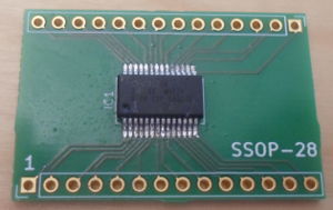
CY8C9520A (Farnell 2630773; data-sheet) is a slightly unusual I/O Expander in that it has 20 GPIO pins rather than the usual multiple of eight. I was originally looking for a 24-bit expander but could not find any, and when coupled with a 74HC238 I only needed 19 bits of output for what I originally planned to use it for. Since Cypress was a brand I had not heard of before, I decided to give the expander chip a self-contained try-out, rather than dropping it straight into a PCB design untested. As it turned out this was a good decision as this expander chip proved to be problematic to use.
Looking at the data-sheet each pin can source 10mA (or sink 25mA), and it seems like the combined current for the pins on each side of the chip is 40mA (100mA if sinking), with a total permitted power draw of 80mA — this works out at 4mA per pin of supply current, which was enough for my original intended purposes. The expander only supports the basic 100kHz I2C speed but this in itself is not a significant limitation. For some strange reason the expander also includes an EEPROM intended for general use.
I2C addressing
The device address selection has an incremental algorithm where the strength of the pull-up/pull-down resisitor dictates whether further pins need to be considered in deciding the I2C address — with strong pulling (under 300Ω) the remaining bits of the I2C address use hard-wired values, which are mostly zeros. However with weak pulling (75kΩ-200kΩ) the next pin is considered an address pin rather than an input/output pin, and sets the value of the next more significant bit of the I2C address. For the simple use-case of using just the dedicated address pin, if it is tied low the I2C address is0x40 and if tied high it is 0x42. The MSB of the I2C address being set normally indicates access to the EEPROM, but if all seven address bits are defined via pin wiring, the MSB of the first register byte is used instead — this bit is cleared for all defined expander commands.
Command set
TheCY8C95xxA uses register-addressed I2C transactions, and supports up to eight ports (i.e. 64 bits), although the CY8C9520A variant only has three ports. Each port has its own registers for input/output and interrupt state, whereas all other port configuration such as drive mode requires the setting of a port-select register. All variants use the same address space, so in the case of the CY8C9520A many of the registers will have no effect. There are further registers for configuration of the PWM functionality, as well as some auxiliary commands. For demonstration purposes an I2C address of 0x40 is assumed, and that transactions are via my I2C-serial adapter, using the associated Python script. I didn't use the usual USB-ISS because it did not work.
Reading & writing
Reading and writing of pin state is done via separate registers, with the output registers controlling the output drives and the input registers indicating actual pin state, so in some circumstances it is possible for a pin to act as both input and output at the same time — for instance when an output pin is configured as pull-up or pull-down, an external stimulus can override the driven output resulting in a different input read value. Reading is via registers 0-7 and writing via register 8-15 — the following sets all pins on Port 1 to input, reads from this port, and then writes0xcdto Port 0:
./ttyI2C.py /dev/ttyUSB0 40 1 18 1 1 ./ttyI2C.py /dev/ttyUSB0 40 1 1c 1 ff ./ttyI2C.py /dev/ttyUSB0 41 1 1 1 ./ttyI2C.py /dev/ttyUSB0 40 1 8 1 cd
For input pins there is also per-pin option of inverting the logic:
./ttyI2C.py /dev/ttyUSB0 40 1 18 1 1 ./ttyI2C.py /dev/ttyUSB0 40 1 1b 1 ff
Drive mode
Somewhat unusually for an expander chip, there are several options for how logical output levels are translated into electrical signals: Pull-up, pull-down, strong drive (i.e. Vcc or Ground), and open drain. By default a logical-high output activates a circa-5.6kΩ pull-up to Vcc and a logical-low is a direct connection to ground — coincidentally a combination that allows this expander to drive LEDs without an external protective resistor. Drive mode is configured per-pin and the desired drive mode is selected by writing a bit-mask corresponding to the pin(s) to the appropriate drive mode register — the corresponding bit in the other drive registers is cleared. The different modes are summarised in the table below:
| Mode | Register | Logical Hi | Logical Lo |
| Pull-up | 0x1d |
Vcc via resisitor | Ground |
| Pull-down | 0x1e |
Vcc | Ground via resisitor |
| Open-drain High | 0x1f |
Current source | High-Z |
| Open-drain Low | 0x20 |
High-Z | Current sink |
| Strong Drive | 0x21 |
Vcc | Ground |
| Slow Strong Drive | 0x22 |
Vcc | Ground |
| High-Z | 0x23 |
High-Z | High-Z |
The open-drain high mode is slightly confusing as it actually sources current rather than sinks it. From what I can gather “slow” strong includes a capacitor that increases rise-time from a maximum of 18ns to a typical 30ns, which reduces harmonics but is unsuitable for switching speeds of more than 1MHz. The following sets half the pins on Port 0 to pull-up and the other half to open-drain low:
./ttyI2C.py /dev/ttyUSB0 40 1 18 1 0 ./ttyI2C.py /dev/ttyUSB0 40 1 1d 1 f0 ./ttyI2C.py /dev/ttyUSB0 40 1 20 1 0f
Interrupts
Each port has its own interrupt state register, and these are registers 16-23. Interrupts are asserted when a pin changes, and interrupts are latched so they remain asserted until the corresponding interrupt state register is read. The following sets Ports 0 & 1 to all-inputs and clears the bit-masks so that all pins can raise interrupts:./ttyI2C.py /dev/ttyUSB0 40 1 18 1 0 ./ttyI2C.py /dev/ttyUSB0 40 1 1c 1 ff ./ttyI2C.py /dev/ttyUSB0 40 1 19 1 0 ./ttyI2C.py /dev/ttyUSB0 40 1 18 1 1 ./ttyI2C.py /dev/ttyUSB0 40 1 1c 1 ff ./ttyI2C.py /dev/ttyUSB0 40 1 19 1 0
Taking advantage of the interrupt registers being sequential, the following will read the interrupt state for both of these ports:
./ttyI2C.py /dev/ttyUSB0 41 1 10 2
Pulse-width modulation
Pulse-width modulation is basicaly output of a square wave, the parameters being the period & duty-cycle (i.e. what portion of the square wave is logical high). Pulse-width modulation functionality is something I will cover in a future article, as I feel it is better described as part of a practical use-case.EEPROM protect
The EEPROM can be made read-only, have write disabled via a pin, or be disabled completely. As a supposed guard against accidental changes, the register that controls these protection options requires a 3-byte unlock prefix to be written before the register's new value. To me this all seems overkill, particularly as including EEPROM support in the first place is somewhat baroqueWatchdog
If enabled, which is done by writing a non-zero value to register0x2f, the watchdog timer resets the chip if no I2C transactions occur within the specified time. This timeout is in seconds, although the data-sheet gives variance bounds of -50% to +100% which to me seems pretty large. For an I/O expander this to me seems like an extravagance, as I cannot think of any failure cases where it would be useful.
Device ID & status
This is a read-only register that indicates which variant of the chip within theCY8C95xxA device family, and whether the start-up configuration is factory default or a custom user configuration stored on EEPROM. Suppose it is required as the entire family have an otherwise identical communication interface, and it makes a convenient read-test just to make sure I2C transactions are working.
./ttyI2C.py /dev/ttyUSB0 40 1 2e 1
Configuration loading & saving
The configuration can be made persistent by storing it to EEPROM, so that on the next power-up (or reset) the device does not revert to factory defaults. It is also possible to read/write device configuration as a single 146-byte data block, either straight into the EEPROM persistent store or straight into the current configuration. These are done via commands through register0x30, but since my I2C-serial adapter does not currently support transactions that large, I have not tried them out myself.
EEPROM
TheCY8C9520A includes 3 kilobytes (the other variants have more) of general-use flash memory, arranged into 64-byte pages, although read/writes do not need to be page-aligned. In most cases an incoming I2C transaction accesses the EEPROM of the MSB (i.e. A6) if the device address is set; however if bit A6 of the device's I2C address is set via pins, whether a transaction is an expander command or an EEPROM access depends on the following register byte — if it is set the bit is masked out when calculating the EEPROM address. I have no personal need for the EEPROM functionality, so did not test it out to any serious extent.
Chip problems
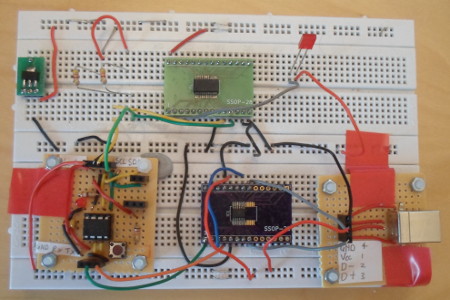
For some reason theCY8C9520A would not play ball with the USB-ISS I2C master I normally use for testing I2C devices. A total of four of the expanders were soldered to breakout boards, but none of them would respond to basic test transactions sent from the USB-ISS, even though things like idle-state current draw through Vcc were well within values stated within the data-sheet. I even ordered some from Digi-Key just in case Farnell had a dodgy batch, but the results were all the same. Given the high unit cost I did not want to simply discard them all, but there is only so much you can check and re-check a data-sheet for mistakes in wiring. In the end I built my own I2C master, which was able to successfully communicate with the expander. My working assumption at the time was that the 4.7kΩ pull-ups built into the USB-ISS were too strong (i.e. resistance too low), which was why my own master allowed the resistors to be changed, but a quick test showed that the pull-up resistance was not the source of the problems.
The USB-ISS is based on a Microchip PIC18F14K50, so I am at a complete loss as to why it had problems whereas the PIC12F1822 did not. As a result I spent far more money than I needed to in trying out this chip, including ordering in extra breakout boards, and that alone leaves a reluctance to recommend it.
Remarks
Compared to other expander chips theCY8C9520A has what I can only consider to be pathological levels of flexibility, which results in a part that is both relatively expensive and overly complex. Having a multitude of drive modes for instance is nice, but in most circuits I would select a chip that supported just the mode I needed. Defining all I2C address bits via pins leaves only 14 for input/output, in which circumstances I would opt for a 16-bit expander such as the PCA9655E or PCA9671. Only supporting the base-line 100kHz I2C is also a bit of killer, which sticks out like a sore thumb alongside all the other features. An interesting chip, but one that feels like it is trying to do too much, rather than targeting a subset of use-cases.