Reflow soldering hot-plate
30 December 2023These days I have a preference for hand-soldering over reflow soldering but an upcoming project of mine involves QFN (Quad Flat No-leads) chips that in some cases are impossible to hand-solder, and rather than experiment with hot-air soldering I opted to revive my hot-plate reflow control project. This sort of project brings together a lot of different things and a large portion of the circuits made during lockdown were related to power control and temperature measurement intended for potential eventual use in such a project. In the end it turned out that much of the automation was not actually required for the task, but these projects are as much about process as outcome to there is no wasted effort.
Hot-plate evaluation tests
Back in late-2020 I obtained a SunavCB-H21 portable hot-plate and at the time did some temperature tests but since then it had become clear that the 1.5kW power rating coupled with a high thermal mass made it difficult to control with any sort of accuracy.
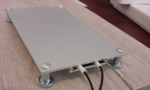
My plan was to build my own hot-plate but in the search for suitable heating elements I came across the YG400W-N which is a pre-made rework heating plate that uses a PTC (positive temperature coefficient) heating element — maybe a bit small but otherwise exactly what I was looking for.
Amazon lists it under the brand name QOTSTEOS but in reality I think this name is just something that the vendor uses for various white-label goods.
As with a lot of Chinese-made goods of unknown pedigree some caution needs to be taken with specifications and certainly the wires that connect to the heating element look rather thin for the supposed power rating.
Initial testing was to see how quickly it would heat up with an uncontrolled power supply, and based on the 220-volt 400-watt rating giving an expected current draw of 1.8 amps it was wired up to a plug with a 3 amp fuse. Starting from room temperature the current draw spiked to 4.3 amps which seemed to be around 35-45°C but apart from that second or two the current draw was below 2 amps, with the temperature reaching 100°C in a bit under ten seconds and 200°C after 34 seconds, with a noticeable slowing down around 150°C. This is in line with what the device claims it can do but is far too fast, reaching in twelve seconds what the reflow profile for my solder paste expects to take almost two minutes, which led to the working assumption of AC power needing to be reduced to around 10% mains voltage.
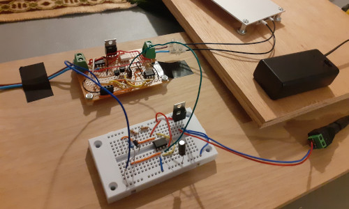
Power control experiments
The next experiment was limiting the amount of power available to the hot-plate in order to reduce the warm-up time in order to find setting that gives the desirable thermal output of a degree or two per second. Power control used an opto-isolated triac triggered by the phase-signalling circuit from mid-2021 together with safety isolation, and this experimental setup is shown in the picture below. This circuit limits power by only allowing a portion of the AC oscillations through to the hot-plate and hence only a portion of the available power. Given the working-assumption target of 10% use of a step-down transformer was considered but a suitable one at reasonable price was not available at the time.
I suspected the maximum pulse that the control board could emit was not long enough for the main power triac to activate so an extra circuit with a 555-based monostable timer was added to increase the pulse duration. With this setup the rate of heating is not entirely consistent and is still a touch too fast at some temperature ranges but it proves that under-powering the hot-plate this way works, and at least it provides a rate of temperature increase that is manageable. As a follow-up the control circuit was replaced with an astable 555 timer with an approximately 10% duty cycle — it used recycled components at hand rather than digging though stock for exact values — and it gave much the same results. An advantage with the latter is the elimintation of the isolation transformer used by the zero-crossing detection within the control circuit.
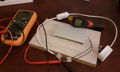
Hot-plate surface temperature
For controllability an important factor is the intertia between powering-down the hot-plate and peak temperature. With the hob experiments this was often in the order of 20-30°C which meant that control was pretty much timer-based and mostly open-loop. Using the infra-red thermometer the overshoot with the hot-plate was under 10°C and the temperature would quickly drop back to the reading at the time power was turned off. Human reaction time would have been a factor in this manual experimentation so prima-facie these are good results. Aside from a small area a centimeter or so from the edge opposite where the wires are attached, the temperature across the heating surface was consistent. Temperature readings from the infra-red thermometer were then compared with readings from a thermo-couple.
Realistically the only place the therocouple could have been secured was to be shoved in beside the heating element as shown, but putting it right next to this in hindsight was not ideal. Thermocouple temperature calculations were done using the prototype automated temperature control that was previously built but never completed. These readings were a degree or two different from the infra-red reading which is about the expected accuracy of K-type thermo-couples, but the important thing is the relative ease that a set temperature can be maintained to within a few degrees with just manual control. Easy manual control bodes well for the automation of the heating process.
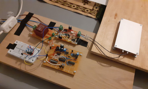
Prototype reflow control
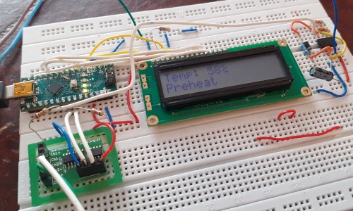
Much of the complexity with the automatic reflow control circuit built back in 2020 was drawing of the graphical display rather than the control algorithm itself, so a new prototype reflow control circuit based around an Arduino Nano was wired up that instead used a much simpler text-only LCD display and this is shown below. Part of the motivation was the suspicion that making full use of the graphical display would never actually happen so it made sense to do away with the extra cost and complexity a graphical display brings with it, and overall using this new prototype was less of a headache then trying to adapt the previous makeshift-ish control circuit.
Heating profile test
A five-stage algorithm was implemented to see how well the hot-plate could be kept to the ideal reflow profile. This algorithm consists of a pre-heat up to 120°C and once this temperature has been obtained it enters a ‘soak’ phase where this temperature is maintained by turning on heating if it falls below 118°C and off again once it is back to 120°C. After a 100-second soaking time the temperature is ramped up to 170°C where the temperature is then maintained at this level in a ‘reflow’ phase; this lasts for 50 seconds after which heating is turned off for cooling down. These phases are marked on the graph below that shows the recorded temperature over a test run.
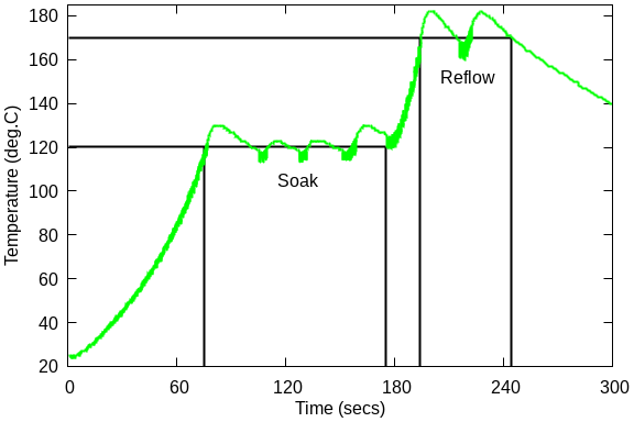
These are good results with tight bounds of the oscillations in the soak stage, and while there is some overshoot at the end of pre-heat and ramp-up it is manageable. Notably there is more variation in temperature readings during the 170°C reflow than there is in the 120°C soak but it is within bounds of the temperature range that needs to be maintained. There are ways this could be tweaked but these results are already well within the ball-park of where they need to be and are far better than those obtained with the previous hot-plate. The experiment was re-run using 150°C and 220°C as the soak and reflow temperatures respectively and as shown in the next graph things are not so good.
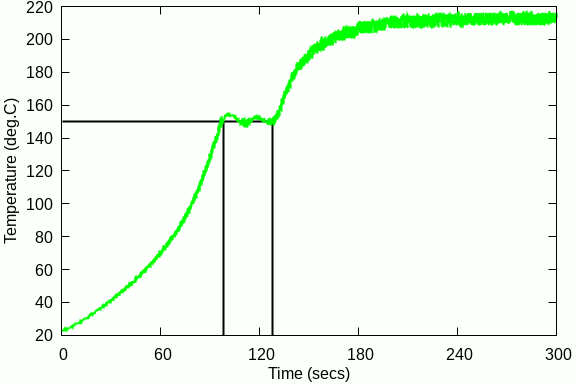
The heating element is non-linear with a combination of the internal resistance and the amount of power supplied by the triac being insufficient to raise the temperature upto the target 220°C, falling just a few degrees short. This setup was already struggling above 180°C and it is clear that having a target reflow temperature much higher than 170°C would require the ability to increase the amount of power the triac supplies.
Heating limit
A final test was done with the triac hard-wired so the hot-plate is always on and this resulted in the heating profile shown below, where the rate of temperature rise is noticeably tailing off above 180°C and tops out at 230°C. This is notable because using full-power only got the temperature about twelve degrees higher than what was obtained with ten percent power. In one sense it is good that even at full power the hot-plate temperature will not go up to temperatures where PCBs will start to burn, but the temperature it did get up to is significantly below the 240-260°C the hot-plate was advertised as being able to reach.
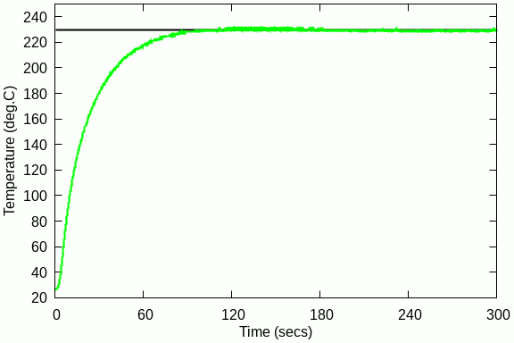
Peak temperature was significantly below the 240-260°C the hot-plate was advertised as being able to reach and the 90 seconds it took to top out was three times what was specified, but being a no-name Chinese good that to be fair was quite cheap this sort of fibbing is to be expected. A major consequence of the hot-plate not exceeding 230°C and with the rise in temperature slowing down a lot above 180°C is questioning the value of having any sort of automatic power control. With a sufficiently slow rate of temperature increase having a soak stage is not going to be required, and with a natural temperature peak it bring the question whether closed-loop temperature control is worth the complexity over just using a timer.
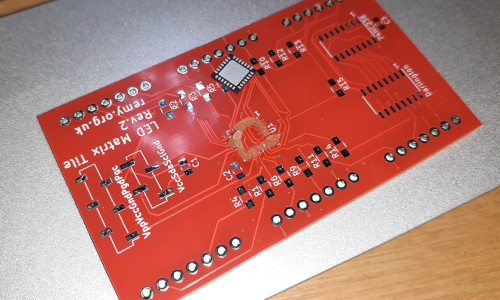
Manual reflow soldering
Since it seemed that reflow soldering could be done with the hot-plate without any form of automatic control the thing to do was actually try using it this way, and this is exactly what was tried in order to solder a QFN micro-controller. This process was experimental with chips needing to be removed and redone but in the process a technique became apparent: Firstly place flux paste onto the pads and then turn the hot-plate on; once the PCB was up to temperature and the flux melted to liquid touch some solder wire onto the pads in order to tin them; then place the QFN chip onto its foot-print and adjust it into place as needed; finally switch off the hot-plate and allow the PCB to cool down. Some PCBs were moved off the hot-plate and the chip pressed down with tweezers while the solder solidified but it is unclear whether this made any practical difference.
One hazard is using too much flux and first time round this resulted in poor connectivity since the chip was not flush with the PCB — the mistake was hand-tinning the pads with a soldering iron prior to putting down the flux. However an advantage with tinning the pads with solder wire rather than using solder paste is the pads only attracting just the right amount of solder and this makes solder bridges unlikely. Should things go wrong the lack of leads makes rework relatively easy, as unlike QFP and TSSOP there aren't any fine-pitched wires that are a pain to remove solder bridges from when desoldered.
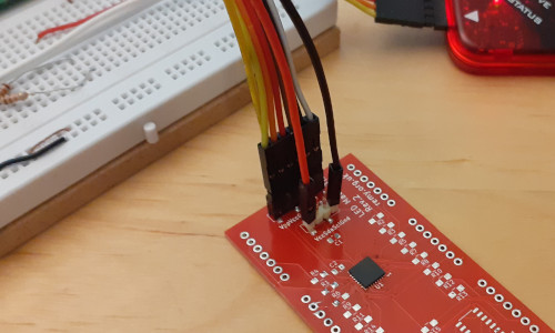
A quick check of the chip is to see if the Microchip flashing utility can connect to it, which if is the case means that pads on two sides of the chips have good connections and hence is going to be flush with the PCB. This is not a thorough test but checking of all the individual pins is beyond the scope of this experiment. Given how smoothly it went I am no longer as adverse to getting QFN chips as I was up until now, although further experimentation with the amount of flux is needed as I suspect just the flux core within the solder wire might be sufficent.
Remarks
Unlike a stove hot-plate where close attention has to be paid to the heating process, using theYG400W-N with just power control to slow down the rate of heating was both a quick and forgiving process, and even without power control it went as well as could be expected.
Given the relatively good experience of using the hot-plate manually and the rarity of using components like this that really do need reflow soldering the follow-up of building a ‘production’ PCB-based reflow control circuit no longer seems worth the effort.