Triac triggering pulses
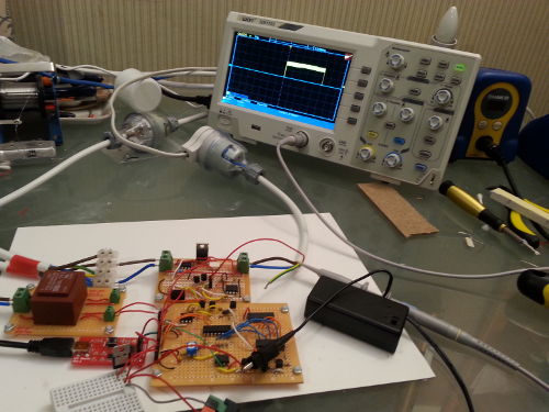
31 January 2021When the most recent triac control circuit was completed one thing that was omitted from the experimentation was trigger pulse generation, and I have now finally got round to actually performing such testing. This is part of end-to-end testing with an actual mains AC load, although it is a filimant lamp rather than the hot-plate that started off this series of projects. The whole test setup is shown below:
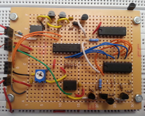
Main control circuit
The blocking capacitor on the main control circuit was replaced with one of lower value in order to narrow the intermediate phase trigger pulse, which from experimentation means that the trigger pulse has a stable minimum width of 600μS, and this is below what I suspected would be the required trigger width. It also includes the trigger pulse generating 555 that was previous omitted due to the lack of a suitable potentiometer.
High-voltage interface
The high-voltage interface circuit was repurposed as just a switching circuit by bypassing the on-board 555 and feeding the trigger pulse directly into the optotriac, as this was the most expedient way of interfacing the main circuit with 240-volt AC mains and allowed me to get one more use out of a circuit that I have otherwise decided to abandon for safety reasons. At some point I will build a PCB with just the optotriac but for the time being this is not a priority of mine.
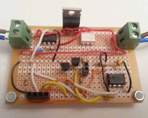
As an aside the 78.8kΩ on the H11AA1 optocoupler should really be rated for at least 730mW rather than 250mW, so I disabled that part of the circuit by desoldering one end, but the 360Ω resistor attached to the optotriac is fine.
Since activation of the phototriac happens during the low-amplitude part of the mains AC cycle, and once the main Triac has fully activated there is a maximum 3-volt drop across it, the 360Ω protective resistor will never have the full 240-volt mains dropped across it so its 250mW rating is not an issue.
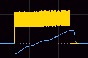
Measuring the trigger pulse
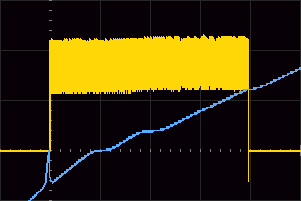
Although there is a lot of distortion the two traces below show AC output with the trigger pulse adjusted to be just below and just above what is required to fully activate the phototriac. In this case the AC supply was the notional 12-volt output from the isolation transformer and the measured voltage was across a 9.36kΩ resistor, with the required activation pulse being 800μS in duration. Potential issues with ground loops mean that I will be using a filament light bulb rather than an oscilloscope to check whether the pulse is sufficient to activate the phototriac with 240-volt mains power, but conceptually I would expect the same behaviour as with 12 volts.
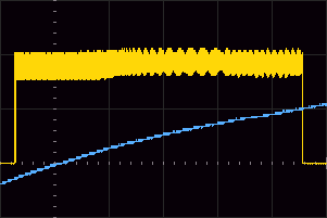
A bypass capacitor fixes the noise although it did not significantly affect the circuit other then the elimination of the noise, so I did not bother with new oscilopscope screen grabs. With the trigger signal being used to switch 240-volt mains the required pulse width is 1.08mS as shown below which is rather more than I was expecting; with higher AC voltages I was expecting it to be lower than that obtained with 12-volt AC. I finally got around to measuring the width of the trigger pulse in the original circuit and the 786μS pulse width obtained indirectly was accurate, which adds to my suspicions with the 1080μS width requirement in the latest experiment.
My major concern is that a minimally-processed phase pulse of 800μS is not enough for some AC mains loads, which spoils my plan of omitting the trigger pulse 555 timer entirely.