Arduino timer
25 August 2025Having pressed back into service the LCD-based timer that was completed just over four years ago several issues with it were noticed, and rather than trying to rectify these problems it was decided to start over and create a new timer. Unlike the previous timer projects this was not intended to be an electronics-focused project so it was based around an Arduino Nano rather than a Microchip PIC micro-controller, and made use of an off-the-shelf self display module. At an early stage it was also decided that alarm sound generation would be done entirely in firmware rather than using 555-based oscillators, and below is the result.
The creation of an Arduino based timer circuit was originally intended to be an expedient means to an end particularly since it negated the need for external programming tools or voltage regulation, with the real focus being the craft side of creating a new enclosure. However the craft part was soon spun out as [a parallel project] due to the firmware part becoming more involved, and the possibility of ongoing experimentation into different enclosures.
The previous timer device
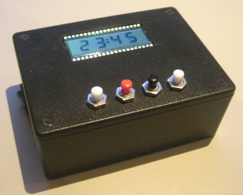
The existing timer circuit was an evolutionary project that started with experimentation in early-2018 and three years later finished as a lockdown-era maker project. Had world history been very different this would have eventually evolved into a gift to my future parents-in-law and the original intention was for it to be ready in time for my 2019 trip to Korea, but in the end was finished in 2021 just before what even at the time was expected to be a tough part of lockdown. Sentiment aside it ended up being unused for a few years following my emigration back to Britain but earlier this year bought it up to Manchester on one of my three flights from Heathrow since the oven in the apartment was proving unreliable.
After what seemed not that much use with a supposedly fresh pair of power cells the timer's sounder could not be heard even though all other functionality was fine. Leaving aside the rather wasteful use from needing to replace them so soon the power cells were also a pain to change due to the things being surprisingly difficult to prise out of the cell holder. Suspicion fell on the way one 555 timer was powering another possibly requiring a voltage level that was breached early in the button cells' life-time, but ultimately the peak 15.37mA power consumption for ten or so seconds was likely not what button cells were designed for. One of the two cells was later reused in a digital thermometer where it barely lasted a month so they were clearly close to depletion.

Samples of holders and compartments for larger batteries had been ordered in at the time but unsure why none were used, especially since there was easily space for any one of them, but rather then retrofit one of them it felt like the time to build a new one had come. There was no desire to potentially wreck the existing case and starting over would also allow rectification of minor annoyances with the push-button interface.
Alarm tone generation
With little documentation available for reference and the passage of time my best guess is the sounder circuitry being a direct reimplementation of an experimental 555-driver sounder built back in mid-2018, which used the output of one 555-based oscillator powering a second audio-frequency oscillator circuit. Using the former to switch the alarm tone on and off rather than do this in firmware was probably done to make the project that bit more electronics-focused, which is a bit dogmatic but this project was about keeping sanity at a crazy time rather then deep thinking. Whatever the reason the tone it gave out was one I wanted to replicate.Sound analysis
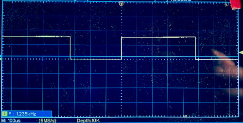
Spectral analysis of the tone generated by the existing timer using Audacity gave different results every time such as when using different microphones and there was a persistent problem of background noise, but typically there were two dominant frequencies of around 1.2kHz and 2.45kHz with the lower of these usually being stronger. The higher frequency is not far off the sounder's resonant frequency of 2.4kHz which is likely why this harmonic is sometimes stronger. Eventually having hooked up an oscilloscope to the tone-generating 555 chip the driving signal was found to have a mark-space of 480μs and 330μs for a period of 810μs with a duty cycle of 59.3% which corresponds to a frequency of 1.235kHz — not far off the results from Audacity.
I am unsure whether the duty cycle is supposed to matter to how a tone sounds but based on the very little testing done in passing with a 50% duty cycle rather than 59.3% the former was significantly quieter, and having noted this no further attention was paid to using equal mark and space periods. The assumption was that it only affected loudness but being happy with what the 480μs/330μs values generated there was no motivation to research and/or experiment with regards to this.
Circuit rebuild
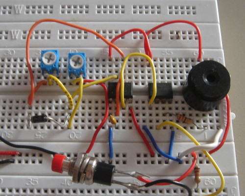
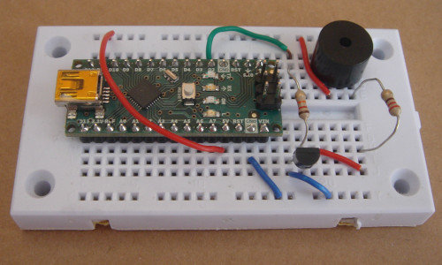
The tone-generation circuit was rebuilt on solder-less breadboard but with the addition of a diode to allow better control of the output wave-form, which was tuned to the 480μs/330μs mark-space time obtained previously and the measured resistances ofR1 & R2 were 5.64kΩ & 4.93k Ω respectively.
These were not far off the resistance values calculated by the 555 duty-cycle calculator once a coefficient in the formulae had been corrected.
The tone generated was not quite the same as the original timer tone but the 20kΩ trimming potentiometers were oversensitive and quite likely other factors such as muffling by the enclosure were also playing a part.
There was no noticeable difference between using the ABT-414-RC and the larger ABT-416-RC sounders.
Conveniently the NAND chip was open-drain so it replaced the output transistor pair used in the original timer as well as acting as an output gate, although a plan to obtain better tunability by using trimmers with a lower resistance range together with fixed value resistors was not done due to lack of suitable components. Due to such logistics and an early decision to move tone generation entirely into firmware, a planned reimplementation on perf-board was eventually dropped.
Firmware-based sound generation
The plan was always to have the intermittent part of alarm generation in firmware but at some point it was decided that the whole lot including tone generation would be implemented this way, leaving the electronic circuitry to consisting of only the sounder itself, a switching transistor, and two current-limiting resistors. Rather than doing trickery of pollingmillis() and micros() and keeping track of time deltas as is done by button debouncing, the timer interrupt functionality of the underlying ATmega328 on the Arduino Nano is used.
I am generally reluctant to invest effort into functionality that is specific to certain models of Arduino particularly as the chip-sets they are based on are not ones of any interest in themselves, but timers are the one exception where the level of effort and non-portability is worth-while.
The implementation of alarm generation mirrors how the two 555s operated in the earlier circuit with Timer1 controlling how the alarm sound is intermittent by enabling/disabling Timer2, with the latter timer generating the oscillations that drive the sounder to create the alarm tone. Timer1 uses CTC (Clear Timer on Compare) mode where upon the timer reaching the value within the compare register an interrupt is raised at which point the interrupt handler can enable/disable the second timer as appropriate and set the compare register value for the next cycle. Within this mode the timer is automatically reset to zero by the hardware. It is up to the firmware to keep track of things so that the correct compare value is set for each intended waiting time, which is 550ms of the sounder being active and 260ms of it being silent. The code below outlines the bare essentials.
void alarmOn() { cli(); TCCR1A = 0; TIMSK1 = bit(OCIE1A); TCNT1 = 0; OCR1A = 8593; // 550ms TCCR1B = 0b00001101; sei(); } void alarmOff() { cli(); TCCR1B = 0; sei(); } ISR(TIMER1_COMPA_vect) { if( AlarmSound ) { OCR1A = 4062; // 260ms AlarmSound = LOW; } else { OCR1A = 8593; // 550ms AlarmSound = HIGH; } }
Initially the same approach was used for Timer2 but this was changed to Fast PWM mode where the timer directly toggles the output pin when a compare register value is reached, and then the timer continues to increment until it reaches a second compare register value upon which the timer is reset to zero and the pin toggled again. Using this latter mode for Timer2 negates the need for an interrupt handler to do things manually, but getting it working revealed annoying quirks and undocumented gotchas such as having fewer bits for the compare values than is available in CTC mode. These issues called into question whether it was really worth the effort changing the mode for tone generation.
Time display
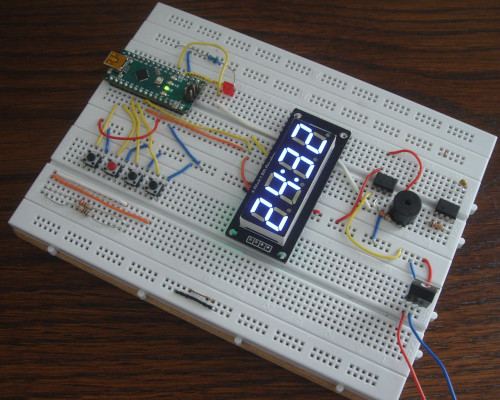
Although there was a stock of partly assembled LCD time displays together with all the components needed to complete them they are a pain to mount within an enclosure, so alternative off-the-shelf modules were sought at least for a first iteration. The one eventually used was an unbranded digital LED module based around a TM1637 driver chip which required only four wires to interface with and had an Arduino library available to drive it, which given the project's requirements of expendience was a major bonus. The module uses a four-in-one LED display which I have come across in the past and had thought of using directly, but stumbling across this ready-made module negated the need to build a boot-strap circuit and write firmware to drive it.
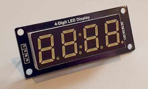
Getting the module up-and-running with the Arduino library was quick enough since it can be installed from within the Arduino IDE, by clicking on the bookshelf icon on the left and searching for TM1637 by Avishay Orpaz. However there are two flaws: The dots are non-functional and it is not possible to show the colon when the lower minute digit is not lit. While non-functional dots are not a concern in this instance the library provided no way to show the colon on its own which means it is not possible to blink the minutes without also blinking the colon. Minor annoyance but not a show-stopper and one that could possibly be patched since the library is open-source. The library is also incompatible with Arduino's Wire (I2C) library.
User interface overhaul
In its deployment as a cooking timer it was virtually unknown for seconds to be used and the lack of a decrement button made the all-to-easy situation of overshooting the desired amount of time particularly annoying. This meant that both increment and decrement buttons were needed but the rarity of settings seconds meant that dedicated second increment/decrement could not be justified, but getting rid of the ability to set seconds altogether was also not considered an option. The outcome of this was to have separate minute and second setting modes and it was felt that in the usual case it would be a nice touch being possible to not use the latter mode at all, which resulted in the following three-button strategy:- Minute setting mode button, which doubles as increment button
- Start & stop button, which also exits time setting modes
- Second setting mode button, which doubles as decrement button
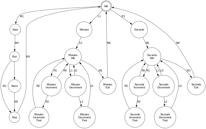
The button press logic is based on the debouncing example within the Arduino IDE, the changes being extending the algorithm to multiple buttons and the use of three button states: Off, on, and held — the latter is when a button has been held down rather than a momentary press. This is used for setting of time delays so that a delay of 30 minutes or seconds does not need 30 separate button presses and was carried over from the previous timer. Since the Arduino has built-in pull-up resistors buttons are active-low and the button press logic inverts this to active-high for consumption by the firmware logic.