555-driven sounder
27 July 2018When I was looking for sounders that would happily operate at 5 volts the ones I found all required a square-wave input rather than DC, and after experimentation with them using the pulse-width modulation of the Cypress I/O expander, I looked for a simple hard-wired solution that the task of generating the square wave could be off-loaded onto. The result is a circuit that uses two TI
NE555P chips (Farnell 9589899), one to generate the square wave itself, and the other to control the on-off intermissions.
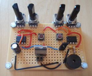
Pressing the left-hand button provides an intermittent tone, whereas the right-hand button provides a continuous one. The jumper should be removed for the latter, otherwise there is potential short-circuit between a grounded pin and the Vcc power rail. Ideally the tone-generating 555 would be controlled via the reset pin, but for simplicity I gate the entire chip.
555 timer wiring
The 555 timer is one of the two integrated circuit chips I remember using from school days — the other one being the op-amp — and consists of an SR flip-flop that is driven by comparators linked to a potential divider. The internal workings are beyond the scope of this article, as there are plenty of other websites out there that explain how it works. Here, the 555 chips are wired up as astable multi-vibrators, which means continuous oscillations rather than generating a a train of pulses in response to an external trigger. Even though there is supposedly a “standard” symbol layout for a 555 — which is what has been used below — it is far from universally adhered to, even in technical data-sheets.

For simplicity control (Pin 5) has been left floating rather than having a decoupling capacitor attaching it to ground.
Period & duty-cycle calculation
There are several calculators for the timing properties of 555 timers wired up as oscillators, but all the good ones had their annoyances so I decided to make my own calculator. The Javascript-enabled table below uses the period and duty-cycle formula from theNE555P data-sheet, which has slightly different coefficients used for generic 555 chips.
| Component | Value | Units | |||
| Resistor R1 | |||||
| Resistor R2 | |||||
| Capacitor C | |||||
| Period | Duty cycle | ||||
| 0.3mSec (3.6kHz) | 67% | ||||
As a rule-of-thumb and using resistors in the 1-10kΩ range, a capacitor of around 0.1μF is suitable for audio frequencies, and a capacitor in the 220-400μF is suitable for frequencies with periods of a second or two.
Overview
There is a small but subtle tone difference, due to differing voltage drops, between using the intermittent and continuous tone buttons — this could have been eliminated by using a switching transistor, but this would have been a significant increase in wiring in this small circuit. The point of using variable potentiometers is so that an “ideal” frequency can be found, but prior to this the tone generated using fixed 2kΩ resistors seemed to be nice enough.When using intermittent time-generation the first tone burst is significantly longer than the rest, which is likely because the timing capacitor is fully discharged, whereas in steady operation it is alternating between two partially-charged states. My general feeling is that while tone-generation is worth off-loading, the intermittent tone on-off duty cycle is something that is better done in firmware, particularly as frequencies on the order of 1Hz need relatively big capacitors.