50% duty-cycle 555 oscillator
16 January 2021Although the 555-driven sounder had an underlying purpose of deciding which frequency of alarm I would use in my much-delayed 2nd gen. LCD timer, it was nevertheless an excuse to try out a timing circuit I had first used back in my school days. However this circuit has the disadvantage of not being able to generate waves with a duty cycle of less than about 60%. Here a slight modification is shown that does allow duty cycles of 50%, in addition to being easier to independently set the mark and space.
Schematic
I got this idea from a Stack Exchange electronics question so I certainly don't claim its originality. The idea is to take the standard astable multivibrator circuit and put a diode acrossR2 as shown in the schematic below so that during the charging phase (i.e. the on-period) this resistor is effectively shorted out.
As a result the on-period is a function of just R1 & C1 and is not affected by R2.
The discharging phase (i.e. the off-period) is the same as the standard 555 circuit.

Usng two identical resisitors should result in a duty cycle that is very close to 50% — the forward voltage of the diode slightly alters the internal voltage-divider within the 555 chip so it won't be exactly 50%, but this difference can be minimised by using schottky diode.
Period & duty-cycle calculation
This calculator is a modification of my previous 555 calculator to use the formula from the Stackexchange electronics answer I got the circuit idea from, which in turn seems to be based on an earlier question that has since been deleted. In practice the difference caused by accounting for the diode's forward voltage will often not be noticeable due to rounding in the calculation.
| Component | Value | Units | |||
| Power | V | ||||
| Diode | mV | ||||
| Resistor R1 | |||||
| Resistor R2 | |||||
| Capacitor C1 | |||||
| On time | 0.7mSec | ||||
| Off time | 0.7mSec | ||||
| Period | 1.4mSec (0.7kHz) | ||||
(Added 16 Aug 2025): Changed selectin of time magnitudes and corrected typo on formula. Compared to a real audio-frequency circuit the mark-space times had a margin of error of 3% which is less than the component tolerance.
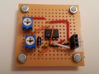
Building the test circuit
The MulticompMC01006 breadboard I used for the test circuit — shown at the top of the page — is one that I had stopped stocking in favour of the slightly bigger MC01007 but in a recent partial stock-take I found that I still had a few unused boards.
The potentiometers are Amphenol N6L50T0C-203-3030 20kΩ trimmers, and the diode a ON Semiconductor 1N4007RLG.
By accident I initially built the test circuit used a 100pF capacitor instead of a 100nF one, and my guess is that the resulting ~500kHz output was too much for the diode as the circuit behaved more like the standard astable 555 circuit where the upper resistor affects both the mark and space of the wave-form.