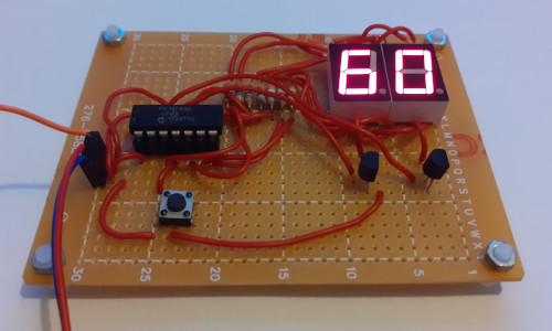
Pulse counter
15 August 2023A simple circuit that counts incoming pulses and displays the number of rising or falling edges detected on an LED display. Based around a Microchip
PIC16F620 it is intended for use in a future project which will involve emitting pulse trains of specific length although it was also an excuse to use up some old stock of components of which most were likely sourced six years ago.
This was supposed to be a short and simple project but it got plagued by faulty components so ended up taking almost two months to complete, but in the end it worked perfectly without any circuit rework.
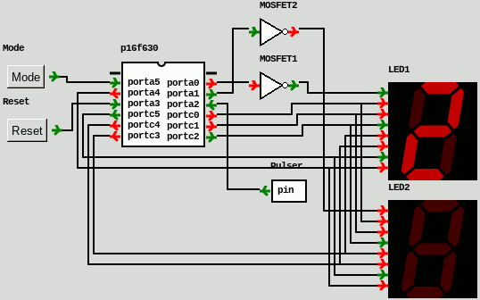
Circuit design
Unusually this circuit was designed entirely in gpsim and the firmware implemented before any hardware work was done, which was due to the project being conceived while on the road mid-June and the firmware itself as ready as it could possibly be without actual hardware by early July. The NOT-gates are used as stand-ins for transistors although an alternative would have been to sink current directly via a microcontroller pin and tristating the pin by switching between input and output modes in order to avoid excessive reverse-voltages across LED segments, although this would have complicated probe-testing of the hardware circuit prior to installing the microcontroller chip.
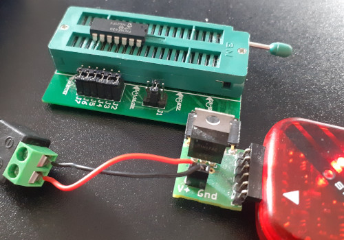
The firmware required minimal changes when hardware became available to run it, and with this expectation the microcontroller was flashed using a chip programming seat rather than having an in-circuit programming header.
Since the thermocouple control was a lockdown-era project for which my recollection was having to use a make-shift rig on solderless breadboard, the last time I used this programming seat would have been late-2018 for the 4-digit 17-segment display.
In situations where space is at such a premium that a flash header cannot be included the preferable solution is to use a SOIC chip flashed using a clip but this has its own set of problems.
Since I no longer use PIC16F88 chips, the DIP packaged microcontrollers I typically stock these days are all fourteen pins (e.g PIC16F1823 and PIC16F1454 ) or less so I am considering making myself a new programming seat with a smaller socket and a built-in power supply.
The PIC16F630 chip
The MicrochipPIC16F620 was the first microcontroller I ever tried using back in 2017 and in hindsight this was probably due to it being a low-cost part easily obtained from E-Bay.
It was a good chip to start with as people starting out are typically only interested in basic digital I/O and this chip has little else in terms of options to trip up the inexperienced, having just the single fixed clock speed and most pins not having secondary functions in addition to bit-banging, and at least for the general-purpose registers there is no need to care about memory bank switching.
It does have its issues though and the last time I used one was back in 2018.
Reliability issyes
In total I got through threePIC16F620 chips by the time the circuit was done and dusted which reminded me of problems I had in my early days of firmware writing back in 2017.
Now some of this may well be down to mistakes on my part but suspicions are that the PIC16F620 has been widely cloned and the units obtained from E-Bay had poor-quality program flash memory if not outright fakes.
I do wonder whether some of my earliest problems were due to using knock-off parts rather than any major fault on my part.
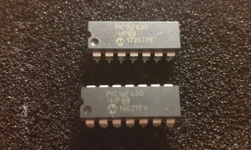
The first was practically dead-on-arrival and the second could initally be flashed but it was throwing up checking and validation errors and it too eventually stopped working completely.
The two dead chips are shown below
The option register
What really gives the game away with regards to the thinking behind the design of thePIC16F630 is the single data-sheet page that documents the OPTION_REG register, and it certainly hints that it dates from a time when expandability was at best an after-thought.
In total it affects four different sets of functionality which is a lot to squeeze into eight bits and these systems are things that are fully independent on other PIC microcontrollers I have commonly used whereas here they are not, and their implementation has introduced subtle inter-dependencies which thankfully I have been able to avoid.
Thee four pieces of functionality are the following:
- Digital I/O pull-up resistors
- Watchdog timer
- Timer0 (generic timer)
- Interrupt-on-change
Interrupt-on-change
It is not clear why but thePIC16F620 has two different interrupt-on-change modes — one specific to the pin RA2 on Port A and another that covers all pins on Port A — but that is what it has and I expect that it is another sign of a chip made to a tight budget.
The first of these is a Schmitt-triggered edge detector although unlike the PIC16F182x it can only detect a rising or falling edge and not both art the same time, whereas the interrupt-on-change that covers the whole port instead uses some mechanisms where the pins are sampled and this is compared with the internal latches.
Only the latter one specific to RA2 is used and this pin is the input pulse train that is to be counted.
Instruction set
While the majority of the Microchip PIC microcontrollers' instruction set is common across at least all the ones I have used, thePIC16F630 omits several instructions that the PIC16F182x family I have normally used has.
One instruction I really missed was BRW which can be used to implement jump tables rather than resorting to if-then-else chains which in assembly gets messy, so the LED segnment lighting code turned into a load of cut'n'paste which is a magnet for bugs.
While the XXX does include an indirection register which is basically a form of pointer it is a pain having only one rather than two, and it does not include instructions the later chipsets have which are intended to aid their use.
For a task like this it would be nice to have a single eight-pin port controlling all the LED segments, since then setting the display would be a simple lookup and writing task, but the PIC microcontrollers that do have such ports are the larger ones that have three or more I/O ports.
Timer0 accuracy
I have had long-standing doubts about how accurate PIC timers are and even if the data-sheets correctly describes them and finally decided it was time to actually check whether my suspicions were well-founded or not. To do this the following simple oscillation firmware was used, which with a prescale of 1:256 and a full 8 bits ofTMR0 before the wrap-around interrupt is asserted should give a delay of 65.536mS:
entry: ; Pin setup BANKSEL TRISC CLRF TRISC ; Lowest 3 bits: 111 = 1:256 MOVLW b'01000111' BANKSEL OPTION_REG MOVWF OPTION_REG ; Enable Timer0 BANKSEL INTCON BSF INTCON,5 mainloop: MOVLW 0xff BANKSEL PORTC XORWF PORTC,1 BANKSEL INTCON BTFSS INTCON,2 GOTO $-2 BCF INTCON,2 GOTO mainloop END
Under simulation this stabilised at 65.537mS but on an actual chip hooked up to an oscilloscope it was giving 56mS which is vaguely ball-park but the 15% deviation makes it more or less useless for actual timing purposes. I have no idea if this chip was from Farnell or E-Bay but I suspect it is likley the latter as I doubt that a genuine part would be that much out of specification.
List of components
The choice of components was biased towards stock that I was pretty certain dated back to 2016, although exclusively using wire from the single reel obtained from Maplin in those early days was perhaps a little dogmatic. Strangely enough the resisitors have actually gone down in price despite inflation and I would not be surprised if one or two others have as well. The one anomaly in this list is the use of MOSFETs for sinking the LED display current as these are the one component that I had no experience with prior until 2021 although I would have taken to them fairly quickly as their high input impedance negates any needs for protective resistors.
| Description | Manufacturer | Part number |
| Microcontroller | Microchip | PIC16F630 |
| 14-pin DIP socket | Amphenol | DILB14P-223TLF |
| 7-segment LED display | Multicomp | LS0565SRWK |
| 390Ω resistors | TE Connectivity | CFR25J390R |
| Perfboard | Multicomp | MC01008 |
| N-type MOSFET | Microchip | TN5325N3-G |
| 22AWG copper wire | Not known | |
| Tactile button | TE Connectivity | FSM4JH |