AT28C64B EEPROM programmer
26 September 2021A natural follow-on from my experimental EEPROM circuit was to build myself an EEPROM programmer, since If i was going to make any real use of such chips I needed an automated way of flashing and dumping them. This project was supposed to be one final pre-emigration project but as things turned out events caught up with me and after much start-stop progress I finally finished the hardware and got round to writing the firmware — the PCB was designed and fabricated back in early May but I only got round to finishing off the soldering just over a week ago so remarks on design decisions are really recent guesses of why I designed the hardware the way I did.

Designed and fabricated back in May this project was intended to be one final one I completed while still living overseas as I did not know how much longer I would be stuck in limbo, but things then moved ahead quicker than expected and it remained unfinished by the time I emigrated. It was only in mid-September that I got round to finishing off the hardware and writing the firmware, and hence bringing the project to completion.
Circuit design
I had originally intended to make use of a Kinetis KE Cortex-M0 but due to the world shortage of ARM cores pretty much everywhere was out of stock with lead times stretching out into 2022. Instead the circuit is based around a MicrochipPIC16F1829 which is the largest chip in the sub-family of PIC16F182x microcontrollers that I am most familiar with.
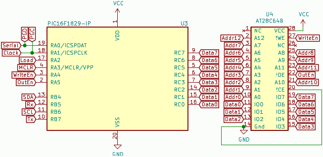
From the outset I decided that all of Port C should be dedicated for data lines, with Ports A & B between them supplying seven pins for setting of address lines and signalling of the EEPROM's control pins — something that would require auxilliary chips.
Even with the latter it was quite a squeeze to get the required functionality and this required some pins on the auxilliary chips to be tied to Vcc or ground.
Like most of the electronic circuits I have had fabricated in the last two years the KiCAD files for this one the PCB are open-sourced in my PCB Bitbucket repository, and the firmware source code for the microcontroller is also available.
Addressing lines
Due to the limited number of pins on the microcontroller some of the EEPROM socket connections have to be driven by external serial-to-parallel chips, and I decided that the connections that would be delegated would be the address lines as I felt that control pins should remain under the direct control of the microcontroller. The74HC595 chip was used due to its very high switching speed, and since I wanted the page part of the address to be handled separately from the lower address bits I was not able to simply chain two of these serial-to-parallel chips together.
While in hindsight I probably could have run two of these chips independently the shortage of pins made me opt for using an PCF8574 I/O Expander for the memory page bits;
since this chip uses open-drain outputs a bank of pull-up resisitors are also required for the address lines it controls.
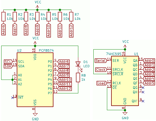
The PCF8574 is more or less the only game in town when it comes to 8-bit I/O expanders, and although in this case the need for pull-up resistors is a pain this is offset by it not needing any configuration prior to use.
While nowhere near as fast as the 74HC595 can be, operating at the I2C speed of 100kHz rather than the circa 25MHz the 74HC595 can have bits clocked out at, the page part of the address bus is set at the start of an EEPROM page operation and is then left unchanged.
Computer interface
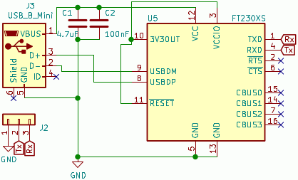
I had long ago decided that an RS232 connection via some sort of RS232-USB adapter is on balance the best thing to use for interfacing a circuit with a desktop computer, so I used an on-board FTDIFT230XS converter chip.
I am not sure where I got the idea from but here the USB chip is powered from the USB interface rather than the main power supply, and as a result the circuit will always be recognised by the host computer whenever it is plugged in; it also allows the rest of the circuit to be power-cycled independently from the USB interface.
In the past I have had a lot of bad luck with FTDI chips in the past so I exposed the internal RS232 connection to the microcontroller via a header — this allowed me to test the USB interface in isolation and should it have failed I could still have use an external TTL-level RS232 adapter.
There is leakage of current across the internal RS232 connection which is enough to raise the circuit's Vcc to 2.2 volts when USB is connected but the main power is off. This does not seem to cause any actual problems since the voltage is low enough to cause a brown-out reset but I do notice that some values in memory survive, and this does make me wonder whether there should be an optical isolator between the USB chip and the microcontroller.
Power supply
These days it is now almost-standard in my designs to supply power via a barrel jack and have on-board power regulation, because in the longer-term it is less hassle. In the past the pricing model of PCBs made it favourable to be stingy with the real-estate and use an external regulated power supply but these days the extra 2-3 square centimeters make little if any difference to cost. I have in the past used the nominal 5-volt power supply that USB provides to directly power circuitry but it is asking for trouble — suspicions are my first-revision I2C only worked properly because it was the only device on the USB bus, and the need for regulation is why so many chips are 3.3 volts.In-circuit serial programming
These days I almost always opt for programming via an on-board header because doing so avoids a lot of trouble compared to the alternatives of either an off-circuit programming seat or an over-chip programming clip. In some cases I have opted for a larger chip such as the 16-pinPIC16F1823 rather than its 8-pin equivilent PIC16F1822 specifically to have dedicated programming connections.
Since there are not enough pins on the microcontroller for some to be dedicated to the programming interface, care has to be taken to make sure that the connections that are shared with the programming header won't have problems with the firmware flashing signals.
This means not using them for things like read or write enable signals.
I opted for the shared connection to be the 74HC595 serial clock and data signals.
Alternative pin assignments
Since the page data lines need to be kept constant throughout an EEPROM flash or dump the chips controlling the page and cell part of the address need to be kept under seperate control. However with only five available microcontroller pins available and a74HC595 needing three of them, there was not enough to give two such serial-to-parallel chips their own inputs, so I resorted to using an I2C I/O expander since it needed just the two I2C signals.
I could have instead used two 74HC595 chips which shared a common serial data signal and had seperate lock & load signals but for some reason at the time I designed the PCB I did not want to make use of shared signals.
This is all the more odd given that I had already taken the step of tying some chip control pins to Vcc and ground but I have long forgotten what I was thinking at the time.
Alternatively I could have tied the clock & load pins together for one or both of the chips and clocked out an extra junk byte, since the 74HC595 data-sheet mentions this situation and states there will not be a race condition.
List of components
The zero-force chip socket for the EEPROM chip was bought from some random E-Bay seller and while I have suspicions over its origin it is good enough for what it is intended for. Most of the other components were bought from Farnell although I think one or two may have come from Digi-Key or Mouser instead; in any case all the parts are listed in the table below. I have not listed the part numbers for the resistors and capacitors because I have long-forgotten which ones I actually used.
| Pad | Component | Manufacturer | Part number |
| U1 | Serial-to-parallel | Texas Instruments | SN74HC595N |
| U2 | I/O Expander | PCF8574 |
|
| U3 | Microcontroller | Microchip | PIC16F1454 |
| U4 | Zero-force socket | n/a | |
| U5 | RS232-USB converter | FTDI | FT230XS |
| U6 | 5-volt power regulator | Texas Instruments | UA78M05IDCYR |
| J1 | 6-way receptacle | Multicomp | 2212S-06SG-85 |
| J2 | Pin header strip | 2211S-22G |
|
| J3 | Mini-USB connector | Wurth | 65100516121 |
| J4 | Barrel jack | CUI Devices | PJ-102AH |
| D1 | Through-hole Red LED | Kingbright | L-113IDT |
| R1-R7 | 10kΩ pull-up resisitor | not recorded | |
| R9-R10 | |||
| R8 | 1.5kΩ protective resisitor | ||
| C1 | 4.7μF capacitor | ||
| C2-C3 | 100nF capacitor | ||
The zero insertion force socket I obtained for attaching an EEPROM claims to be a 3M 228-3345 but looking at its build quality I am pretty certain it is a cheap knock-off.
On E-Bay these things go for £1–2 whereas on the likes of Farnell/Digi-Key/Mouser they are the best part of £20 assuming they are stocked at all.
These days I mostly avoid E-Bay but ZIF sockets are fairly basic components and the build quality has to get pretty bad before they becomes unuseable — the only real precision required in these devices is the PCB pin spacing.
A blown component
Since thePCF8574 I/O Expander had an indicator LED on its unused output pin, one of the first things I did as a smoke-test was adapt some I2C firmware for this circuit in order to control this LED.
The first few times I made some silly mistakes such as copying the I2C setup routines for an I2C slave and getting the I2C write transaction wrong, but then there came a point where I suspected the PCF8574 itself might be faulty.
Rather than go around in circles I desoldered it and then wired it up on solderless breadboard for testing with known-good hardware and firmware.
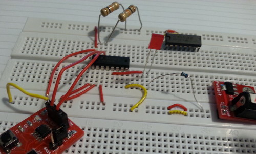
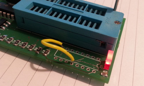
I popped out the suspect chip from the breadboard and replaced it with a fresh one, and the LED shown in the picture above lit as expected. While the footprint on the PCB was unoccupied I tested the LED by shorting it to ground as shown in the picture below, but fortunately it was fine. Incidentally the firmware that was still on the microcontroller successfully lit this LED once the fresh I/O Expander was installed.
Given the circumstances of the time it is plausable that this circuit and/or its components got treated rougher than they should have been. It had been shuttled around in chaotic circumstances, such as having being packed into hold luggage without proper anti-static protection, and some of the soldering was done with a cheap soldering iron at a time when I was likley a bit out of practice.
Microcontroller firmware
Since Microchip PIC microcontrollers are poor targets for C code writing the firmware in assembly is a no-brainer these days. Fortunately the PIC instruction set is very good for the type of timing and pin-toggling that is required from this firmware. The PIC16F1829 is a little unusual in having two I2C modules rather than having a single for which the pins can be reassigned but otherwise the functions for I2C and RS232 were recycled from previous projects with minimal parameter tweaking, so most of the work was implementing the communications protocol and getting the signal timings right. Internally the EEPROM always writes an entire page in one go so the protocol may as well be based around handling entire pages at a time.Split address handling
Since the whole address space of the EEPROM is 14 bits it would require 16-bit variables to store as a single parameter and I very early on decided this was not worthwhile. Rather than implemeting firmware to handle 16-bit values it is logistically easier to keep the higher page bits and lower cell address bits in seperate variables, particularly as the page bits remain the same throughout the actual EEPROM flashing and dumping processes, whereas the cell bits need to be rapidly updated. In practice the only place that actually has EEPROM addresses as a single value is the hexadecimal file format the Python-based control program uses as input and output.Chip clocking & timing
In the past I ran microcontrollers at their fastest possible internally-generated clock speed but these days I prefer to only clock them as fast as they need to be. I normally opt for 2MHz because it is the lowest clock speed that supports I2C, and coincidentally it is also the lowest that supports an RS232 BAUD rate of 57,600. At 2MHz the instruction execution time is 2μs whereas the minimum timing requirements for both the74HC595 and the AT28C64B are 100ns or less, so the firmware does not need any delay loops because there is ample time spent running the instruction doing the toggling.
In fact the only timing requirement that needs attention paid to it is the maximum pulse gap when doing page writes.
Component checking
The first bit of firmware I put together was to try and get RS232 and I2C working, and after thePCF8574 turned out to be blown I wrote some pin-toggling test firmware to check that the 74HC595 was not also damaged.
In the process I also set up a timing loop to test the accuracy of the internal clock since in the past I have seen issues with the accuracy of timer-based delays, but in this case the nominal instruction time was within the margin for error of a quick check with an oscilloscope.
Communications protocol
The protocol for the RS232 interface relies heavily on the linear memory model without which many programming tasks would be unfeasably difficult on PIC microcontrollers. For testing purposes I ended up implementing the ability to read and write individual addresses but from the start a design decision was to only deal with entire pages of EEPROM storage, and it would be a page at a time because the microcontroller does not have enough memory for the full 64kBit of EEPROM capacity. I started with writing the functions for reading/writing this buffer and later decided that I would keep these read/write commands seperate from the actual EEPROM flashing & dumping. The table below summerises the host protocol, which while simple does have some sanity-checking feedback.
| Buffer access | EEPROM access | Direct memory | ||||
| Read | Write | Check | Dump | Flash | Memory load | Memory store |
→ ‘R’ |
→ ‘W’ |
→ ‘C’ |
→ ‘D’ |
→ ‘F’ |
→ ‘L’ |
→ ‘S’ |
← ‘r’ |
← ‘w’ |
→ ‘c’ |
← ‘d’ |
← ‘l’ |
← ‘l’ |
← ‘s’ |
| → 64 data bytes | → page address | → page address | → page address → cell address |
→ page address → cell address → data byte |
||
| ← 64 data bytes | ← ‘.’ |
← value | ← ‘.’ |
← ‘.’ |
→ data byte | ← ‘.’ |
At one point I was going to use ‘.’ and ‘!’ to indicate success and failure respectively but never used the latter due to there being no error detection.
Most of the communications firmware was written before the first time I put an EEPROM seat into the socket, and since there is only a very short RS232 connection between the USB converter chip and the microcontroller I decided not to implement the check command.
The way of thinking
Writing for PIC microcontroller and in particular writing firmware in assembly requires a different way of thinking, and it took a while to get back into the right mind-set. The main things are remembering the snall snippets for things like equality checks and the various ways that the linear memory model operates, but once having got back to grips with those things actually seemed quite easy. Yes there were the odd silly mistakes but that happens with every programming language. I had forgotten how exactly things like timers worked but the data-sheets for these are very concise. Using a debugger to trace the execution of a PIC microcontroller is so painfully slow as to be impractical, so having access to ready-made RS232 routines is a great help — without using the RS232 interface as a debugging side-channel I would have had to use gpsim to make writing the communication protocol reasonably painless, but among the problems gpsim in itself brings it does not seem to support thePIC16F1829.