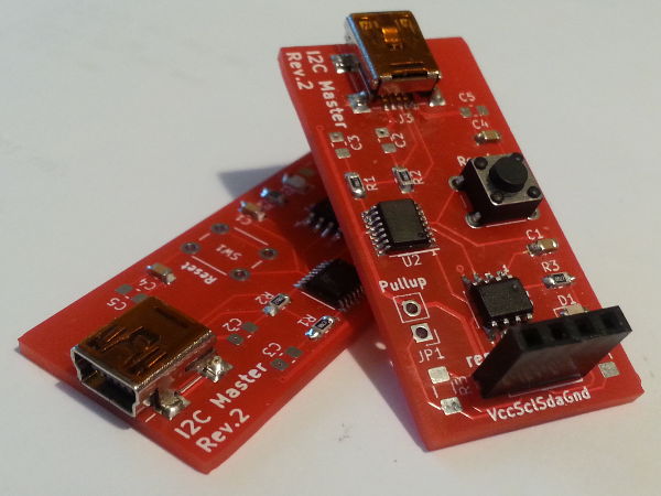
USB-I2C adapter, Revision 2
06 November 2020Although I had already made myself my own USB-based I2C master two years ago, in practice I never really used it that much. Most of the time I needed to use a USB-controlled I2C master it was for evaluating new components and I usually ended up using the Robot Electronics USB-ISS since it had built-in pull-up resistors on the I2C connections, although this also meant always having to remind myself of the latter's idiosyncratic communications protocol. I finally decided to redesign my own adapter to address shortcomings such as this one.
My original prototype I2C master was in response to an incompatibility between the Robot Electronics USB-ISS and the Cypress CY8C9520A I/O Expander that I was evaluating back in mid-2018, and eventually this evolved into a PCB-based adapter that provided a USB interface.
Much like the evaluation testing that was to be the genesis of this adapter its development itself had plenty of problems, and as a result I always had lingering doubts about the electrical properties of the circuit.
I felt it was finally time to address all the issues.
Circuit design
I was going to use some left-overPIC16F1823 chips but since there is no built-in symbol for this in KiCad I opted for the PIC12F18xx that the previous revision used instead.
My recent preference has been to stick to components that are within the built-in libraries since it simplifies open-sourcing the designs.
In any case the schematic for the new revision is shown below.
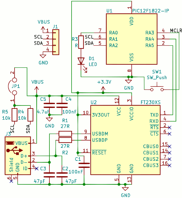
The basic design is carried over from the first version of the adapter but a lot of changes were made, mainly in response to what I have found out since the original was designed back in 2018. These changes are all remarked on within the list of changes below.
- Built-in pull-up resistors
- When testing out new components it is a pain needing to hook up a make-shift circuit for the I2C pull-up resistors, and since this resulted in my previous adapter not being used very often, adding in such pull-ups is the main reason why I made this new revision in the first place. I also included a jumper that allows them to be enabled/disabled because I suspect there are scenarios where they may cause issues.
- Regulated microcontroller power
- I suspect powering a microcontroller straight off the 5-volt USB power lines was asking for trouble, since this was the only time that I have seen a Microchip PIC fail to operate without a bypass capacitor.
Although the
FT230XSis not intended to power other chips the data-sheet states that this is not a problem as long as external components draw less than 50mA, so I used this to provide the microcontroller with a clean power supply. - Passive components
- Even though personal experience indicates many of them are not strictly necessary, this time round I decided to include almost all the passive components the
FT230XSdata-sheet recommends. The main one is the bypass capacitor on the 3.3-volt power output, the previous absence of which may or may not have been a factor in what at the time I put down to a bad batch of chips. The one recommendation I left out was putting a Laird TechnologiesMI0805K601R-10ferrite bead on the positive power line, since this seems intended to stop outbound noise rather than inbound. - USB receptable
- I decided to do away with the full-size USB receptacle and instead opt for a mini-USB one instead. This was as much about trying out yet another connector brand as wanting to use something smaller, and mini-USB feels that bit more robust than the micro-USB ones I have used in the last few projects.
- Reset button
- Even though I don't ever recall using it in production use I decided to keep the reset button, evne though it takes up a significant portion of space.
However since the
MCLRpin has its own internal pull-up on thePIC12F1840the external one has been removed since it was redundant.
List of components
At time of writing I opted to leave some of the footprints unoccupied because I did not have the associated components with me and they were not required for testing purposes — these are marked as omitted in the table of components below. Note that the pin header is a 22-pin strip that I cut to the required length.
| Pad | Component | Manufacturer | Part number |
| U1 | Microcontroller | Microchip | PIC12LF1840 |
| U2 | USB-RS232 converter | FTDI | FT230XS |
| R1,R2 | 27Ω resistor | Multicomp | MCWR08X27R0FTL |
| R3 | 1kΩ protective resistor | MCWR08X1001FTL |
|
| R4,R5 | 10kΩ pull-up resisitor | MCWR12X1002 |
|
| D1 | Indicator LED | Osram | LS R976 |
| C1,C4 | 0.1μF bypass capacitor | Samsung | CL21B104KACNNNC |
| C2,C3 | 47pF bypass capacitor | Omitted | |
| C5 | 4.7μF bypass capacitor | ||
| J1 | 4-way receptacle | Multicomp | 2212S-04SG-85 |
| JP1 | Pin header | 2211S-22G |
|
PIC16F1840 vs. PIC16LF1840
In the past I have had issues with trying to use 5-volt PIC microcontrollers within 3.3-volt circuits, but unlike thePIC16F88 I used back then the PIC12F1840 the chip itself operates fine when supplied with 3.3 volts.
Using an oscilloscope I was able to verify that a test firmware which continually output a single character on the RS232 output pin was doing as expected, but for reasons beyond me the chip would not talk to the FT230XS USB serial converter chip.
Suspecting a voltage problem even though the data-sheets indicated that the I/O voltage thresholds were compatible, I replaced the PIC12F1840 with the low-voltage PIC12LF1840 and things started working as designed.
Issues with the FT230XS
Even though this time I paid close attention to things in theFT230XS data-sheet that quite plausibly were the root cause behind issues I had with the chips two years ago, they nevertheless were still problematic in this project with one of the three I used malfunctioning.
I cannot say conclusively whether it it is due to them being particularly sensitive to damage or misuse rather than actual quality control issues, but for whatever reason they seem to attract trouble whenever I have used them.
There are a lot of fake FT230XS chips around but I would reasonably expect the suppliers I use to source them direct from FTDI rather than stock anything dodgy.
Fabrication
It is not the first time I have used them but this circuit is one of three I had fabricated by JLCPCB in the same order, as I was evaluating them as a replacement for Seeedstudio and on the whole I think they are a much better fit for my needs. The PCBs themselves are slightly more expensive since they are $4 for five as opposed to the $4.90 for ten from Seeedstudio but the vast majority of the time I only ever use one or two of the PCBs anyway; however shipping is where JLCPCB wins out as it is both cheaper and faster. The order went in on a Saturday, was dispatched the immediately following Tuesday, and arrived in the UK via their cheapest $5 shipping option the following week — for comparison even at the best of times Seeedstudio had a three-week total lead time and shipping is typically around $15.I have the suspicion that the PCBs may have been couriered as part of a bulk shipment to an agent in the UK who then dispatched them via Royal Mail. If this is the case then half the total turn-around time was spent with the items already in the country, and I note that a separate PCB ordered from Aisler at the same time had an almost identical shipping time. This is not good news for Aisler since the only reason I still use them is the fast lead time, and JLCPCB's courier options look competitive in comparison.
Firmware
Although the identical core of the circuit means that the firmware from the first revision can be reused, I opted to rewrite the firmware in assembly for reasons that I have already covered in depth — in summary the PIC architecture is one where using it as a target for C code hits it weaknesses rather than playing to its strengths. Over the last two years I have already rewritten all the I2C and RS232 sub-routines in assembly so all that was needed was to rewrite the control protocol. Most of this effort was done using the gpsim setup I used to develop I2C code in the first place although this was not without its headaches — gpsim has plenty of idiosyncrasies and different versions choke on each others' configuration files.Linear memory model
The banked memory model has been my major long-standing compliant with the PIC architecture, as the required bank switching makes it hard to have large data buffers as well as complicating the writing of C with inline assembly. However what I did not know is that the chips also have a linear data memory starting at address0x2000 which contains all the 80-byte bank-specific general-purpose registers as a contiguous block and this is illustrated in the figure below.
To use this area of memory the FSRxL and FSRxH registers have to be filled with addresses calculated manually rather than using labels and letting the assembler work out the addresses.
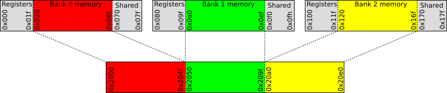
The PIC12(L)F1840 has three general-purpose memory blocks totalling 240 bytes, so FSRxH can be set to 0x20 on start-up and then forgotten about, since altering just the FSRxL register is able to access all implemented areas of memory.
Using linear memory meant that the data buffer could be 240 bytes rather than the 65 of the previous firmware, although I do wonder whether this increase is useful in practice.
Clock speeds
One of the advantages of writing firmware in assembly is that it leaves the coder with a better idea of how quickly instructions need to be executed, and compared to compiled C code that speed is significantly lower, so it is possible to crank down the core clock speed. However in applications such as this the limiting factor is really the serial functions that need the higher core clock speeds in order to operate properly, as the total time the firmware actually spends running instructions outside of busy-waits is basically negligible. The first version of this I2C adapter ran at 16MHz whereas this one runs at 2MHz.
With a 2MHz main clock a BAUD rate of 55,555 can be obtained by using BRGH & BRGL values of zero and 0x08 respectively, which has an error of 3.5% with respect to the standard target BAUD of 57,600.
There is conflicting information regarding acceptable BAUD error with 3.5% seeming to be the upper bound of what PIC data-sheets consider to be acceptable — from my testing it seems fine and I suspect that the FT230XS chip has an oscillator specially selected for RS232 which would cut a lot of slack, but as a general rule I feel 3.5% is pushing bounds.
As for I2C the lowest clock speed that will support a 100kHz signalling rate is 2MHz, although the data-sheet implicitly suggests that 4MHz should be used instead, so there is no point opting for a lower UART BAUD as a trade-off for reducing clock speed any further.