Manual LCD Control
09 July 2021Although control of Hitachi
HD44780 compatible LCD alphanumeric displays was pretty much the first thing I did when I started doing electronics three years ago, I decided to make a control circuit that uses manual switches rather than relying on firmware logic.
This is an approach I used recently for reading/writing EEPROM chips as I felt that resorting to firmware was removing much of the fun from electronics projects.
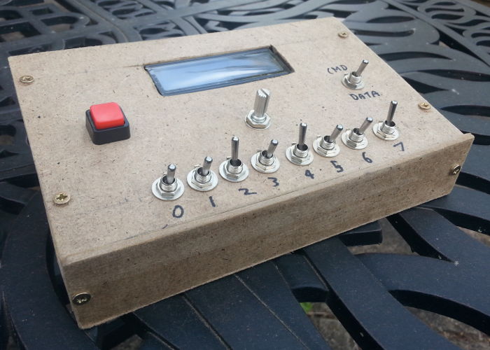
This project was inspired by one of 8-Bit Guy's videos of a similar device being made and the motivation behind this project was really the construction of the mounting rather than the electronics. Originally I was going to use a project box like the one used for my latest timing circuit but it would have at the very least been a tight fit, so I decided to use a piece of unused hardboard instead.
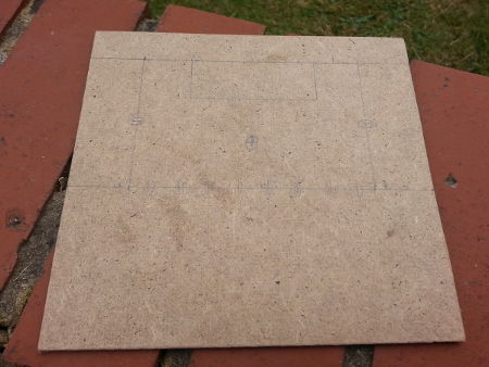
Circuit mounting preperation
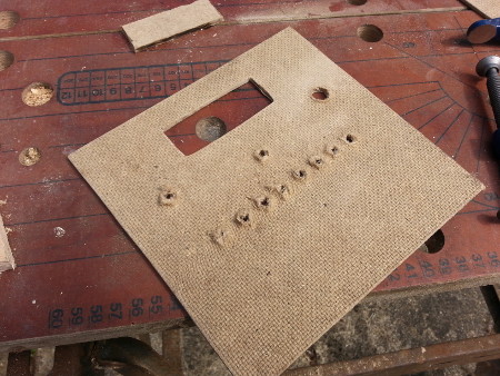
My starting point was a piece of hardboard that was left over from a previous purpose and I decided to make use of the available space to comfortably spread out all the controls, and the plan drawn out on the plywood is shown below. I would later cut a bit off the bottom for a vertically narrower control panel but everything has to start somewhere.
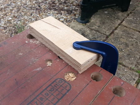
Side supports
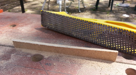
At the outset I had thought about using some extra-long standoffs as support but after spotting some plywood left over from a desk repair that I had the idea of using this instead. In order to make sure the two side supports were the same size I found it easiest to clamp two rough-cut pieces of plywood together and saw them as a single piece, and for controllability I found a handsaw to be better than a jigsaw. While they were still clamped together I used a wood grater to remove any residual differences between the two pieces.
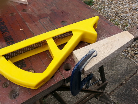
At a later stage I decided to shorten the supports by cutting off the higher part of the slope which was a repeat of the procedure done above to cut the sloping part. Finally a block of sandpaper wrapped around a block of wood was used to sand down the edhes to remove any splinters.
Top panel
In order to cut the slot for the LCD itself I used a Dremel equipped with a blade which was supposedly suitable for wood & plastic, although in hingsight I should have at least used a larger blade. From past attempts at cutting plastic one thing I was aware of is making sure the sheet being cut is clamped down well, but regardless of technique I thought the results were reasonable.
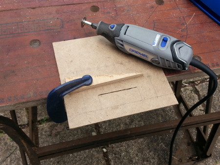
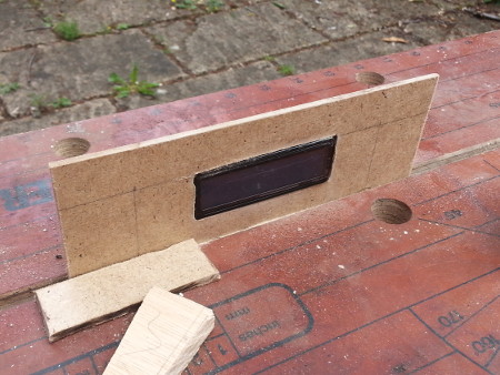
At times I wondered whether the cutting disc was chipping away at the wood or burning it given the occasional smell of burnt wood as well as some charring on the inside edges. I then sanded down the inside edges until the LCD module was able to fit into the slot as shown below, and although it was a tight enough fit to hold the panel in place my plan was to secure the display in place.
Button hole drilling
The next stage was drilling all the holes for the controls, and it shows that I had no prior experience of trying to drill through hardboard. Although I did start off with a 2mm drill bit for the pilot hole I think I would have got slightly better results had I worked my way up through my drill bit set rather than switching straight onto the larger bits. I did not have a drill bit large enough to make the hole for the button on the right-hand side so ended up moving the drill but around the hole to enlarge it — inelegant but in hindsight this is something I should have done with all the holes to get a tight fit for the switches, as they required a diameter that was an odd number of millimetres whereas all the drill bits in my set were of even diameters.
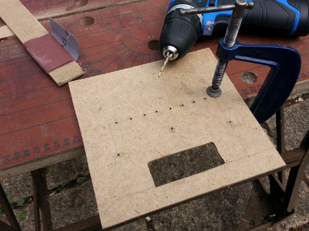
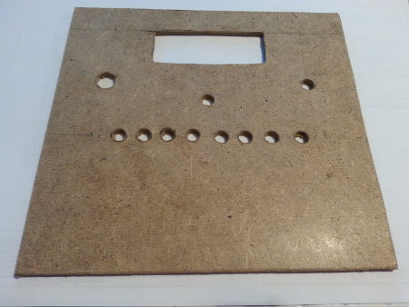
After the drilling the underside looked as shown in the picture below, which I cleaned up by sanding down the indents caused where the drill bits had come through. In hindsight what I should have done is put the hardboard onto a piece of scrap wood and drilled right through so that the edges of the hardboard would have nowhere to bend to, but this is the first time I have tried drilling hardboard so had no technique to follow.
The finished panels
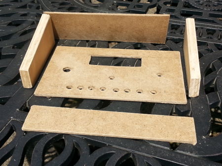
After all the holes were drilled and checked to see that they were big enough for their respective controls I decided to reduce the height of the top panel by 6cm since it was dead space and I preferred something rectangular rather than square. In the process the side supports were also cut short to match, and also added covers for the front and back. All the parts prior to attachment of the electronic components are shown below, although the back panel I would eventually decide not to attach.
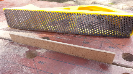
The front panel would prove to be a bit higher than I wanted, so I drew the line where it was flush with the top panel and grated it down as shown below — I had intended to find out what this tool was actually called, but never got round to doing so.
Wiring up the display
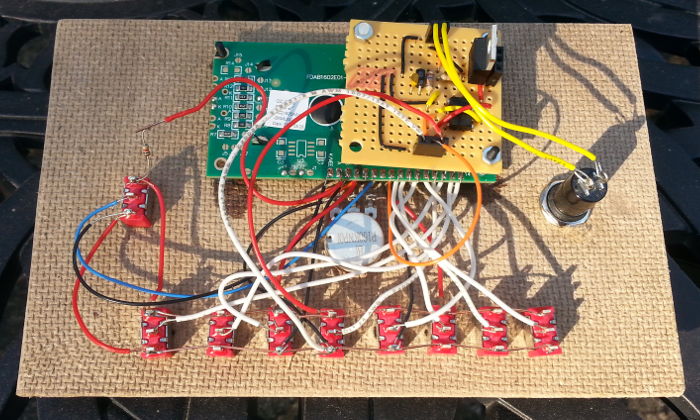
The wiring up of the circuit was pretty much attachment of the various LCD panel inputs to the various manual controls and this is shown in the picture below — as can be seen I did try to colour-code the connections but this broke down a bit in places. It is a bit messy but this tend to happen and the space I provided from the outset turned out to be just about right. The resistor in the top-left I put in to reduce the current draw from the back-light but in hindsight I should have also used a potentiometer for this.
Attaching the LCD panel
Getting the LCD board attached to the underside of the main display panel turned out to be a bit of a pain, as using superglue to attach standoffs to the underside of the control panel did not work out as well as hoped — even with a large amount two of them them became detached and I decided not to try getting the bottom-left one back in place. A difficult part of this process is trying to avoid the superglue getting onto the LCD panel itself, as if that happened an even bigger world of pain would await.
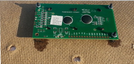
In hindsight using hot-glue from a glue gun might have been a better option, but at the time it was evidently clear that the rough-side of hardboard is basically not suitable for attaching standoffs using superglue. Although from past experience it would have had its own problems, I did wonder whether bolting the panel in place would have been a better option.
Button debouncing circuit
Because the enable signal is something that would be sensitive to bouncing I built a debouncing circuit on perfboard which I ended up bolting on top of the LCD panel since the bolt-holes happened to be a matching distance apart — originally I planned on glueing the board elsewhere on the underside. This debouncing circuit also includes voltage-regulation as there was basically nowhere else to put the circuitry. One irritation is that the LCD panel's enable pin is triggered on the falling edge, so things happen when the big red trigger button is released rather than pressed.Switch sequences
Having the switches on the control panel in little-endian order was a minor mistake since all the data-sheets use big-endian, so I ended up writing the little-endian based summarisation of the command instruction sequences which is shown below. This summation also presents the command sequences in a way that I feel is more useful than how the LCD module data-sheets does so. The major omission being write mode, which no practical application of these LCD modules actually uses.
| Display setup (4-bit mode) | ||
| Code | Action | |
x x 0 0 0 1 0 0 |
Single line | 5x8 dots |
x x 1 0 0 1 0 0 |
5x10 dots | |
x x 0 1 0 1 0 0 |
Dual lines | 5x8 dots |
x x 1 1 0 1 0 0 |
5x10 dots | |
| Display setup (8-bit mode) | ||
| Code | Action | |
x x 0 0 1 1 0 0 |
Single line | 5x8 dots |
x x 1 0 1 1 0 0 |
5x10 dots | |
x x 0 1 1 1 0 0 |
Dual lines | 5x8 dots |
x x 1 1 1 1 0 0 |
5x10 dots | |
| Movement setup | ||
| Code | Action | |
0 0 1 0 0 0 0 0 |
Cursor moves left on data | |
1 0 1 0 0 0 0 0 |
Cursor moves right on data | |
0 1 1 0 0 0 0 0 |
Screen shifts right on data | |
1 1 1 0 0 0 0 0 |
Screen shifts left on data | |
| Control commands | ||
| Code | Action | |
1 0 0 0 0 0 0 0 |
Clear display | |
x 1 0 0 0 0 0 0 |
Cursor home and reset screen shift | |
x x 0 1 0 0 0 0 |
Display off | |
0 0 1 1 0 0 0 0 |
Display on | No cursor |
0 1 1 1 0 0 0 0 |
Underline cursor | |
1 0 1 1 0 0 0 0 |
Blinking cursor | |
1 1 1 1 0 0 0 0 |
Both cursors | |
x x 0 0 1 0 0 0 |
Move cursor left | |
x x 1 0 1 0 0 0 |
Move cursor right | |
x x 0 1 1 0 0 0 |
Shift screen left | |
x x 1 1 1 0 0 0 |
Shift screen right | |
d d d d d d 0 1 |
Set cursor position | 1st line |
d d d d d d 1 1 |
2nd line | |
c c c l l l 0 0 |
Set char data line | 5x8 dots |
c c l l l l 0 0 |
5x10 dots | |
Text data input
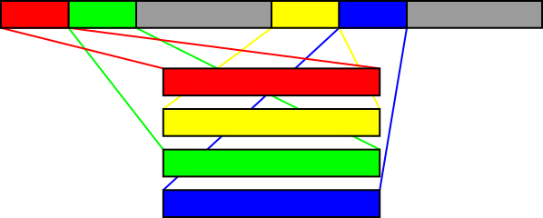
The tricky bit is how the data address space corresponds to actual display output, because the same control chip with the same amount of basically everything is used with a large range of different displays, and it gets particularly confusing with four-line displays. With the 2-line display used here the first line starts at the predictable address zero but the second line starts at0x40; with four-line displays the third line immediately follows the first line, and the fourth line likewise is a continuation of the second line.
This is illustrated in the image below.
Character pixel input
The characters corresponding to the first eight codes (i.e.0x00 thru 0x0f) can be changed.
This is done by using the set char data line which takes a six-bit address where the lower three bits specify the row of pixels and the upper three bits specify which one of eight characters is to be changed.
Once this is set doing a data command sends the switch input to the specified row. Note that only the bottom five bits affect pixel data.
For 5x10 mode the bottom four bits specify the row and the top two specify the character code, so in this mode only four are available for changing.
![]()
Note that once pixel data entry has been done, a set cursor position instruction is needed to redirect data input to the text memory rather than the pixel memory.
As a gotcha in 5x10 mode the bottom bit of text data has no effect, so the four custom characters actually correspond to codes 0x00, 0x02, 0x04, and 0x06.
I suspect this is an artefact of the way 10-row characters are physically stored in memory.
Switching interface mode
In practice the LCD panels come out of reset in 8-bit mode but getting them into a known-mode from an unknown mode is a bit involved. The algorithm is on Wikipeida, which although described differently comes down to getting the device into 8-bit mode from one of four starting states, and then if needed putting the display into 4-bit mode:- Already in 8-bit mode
- In 4-bit mode, waiting for first nibble of any command
- In 4-bit mode, waiting for second nibble of command to switch to 8-bit mode
- In 4-bit mode, waiting for second nibble of any other command
5x8/5x10 settings.