Analogue circuit de-bouncing
06 June 2021Even though push-switch bouncing is an issue I have addressed before it is something I am revisiting since I now have interest in a solution that does not rely on firmware. Additionally I am interested in starting out with a more quantitative view of the problem of bouncing rather than building a debouncer circuit and tweaking component values until is works properly.
Button press experiments
Since the equipment was available some experimentation was done to find out what the transients for button presses looked like, in this case a MulticompMCPS23B-3 push-to-make panel mount button which will be used in my next planned project.
The oscilloscope probe is attached to the output side of the button which is also the high side of a 4.7kΩ resistor that acts as a load, and the power supply is a regulated 5 volts.
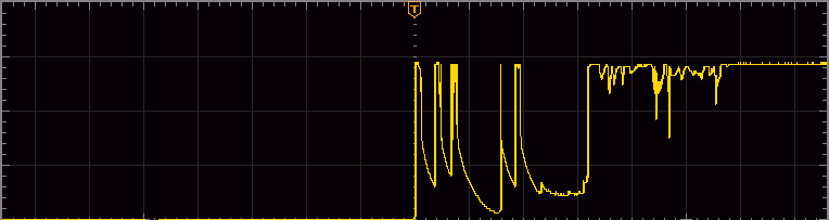
For most button presses any bouncing lasts under a millisecond and quite a few presses don't seem to bounce at all, but occasionally there are some bounces such as the one shown in the trace below that last longer. This trace which has 500μS per division was the worst I was able to capture via experimentation and anecdotally bouncing lasting this long only happens every twenty or so presses.
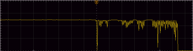
Button release transients are typically shorter than the button press ones, and the longest I was able to capture was the 1.25mS one shown in the trace below; note that a division of 200μS is used in this trace as opposed to the 500μS above. As a result for button releases I am inclined to use 1.6mS as a threshold for button releases.
Analogue debouncing circuit
One approach to debouncing is to use the charging/discharging of a capacitor to delay the signal from a button press/release until it has expected to have stabilised, which is what is done by the circuit shown below. The diode is a trick used previously of bypassing a resistor in one direction so that it does not contribute to the time-constant of capacitor charging when the button is not pressed. The ‘raw’ button press results in an active-low signal since it is a connection to ground but due to the inverting Schmitt trigger the debounced output from a button press is active-high.

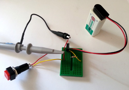
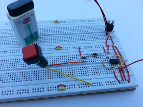
The starting point for value selection is 10kΩ for R1 in order to limit the current flow from Vcc to ground through the button while it is pressed; from this a ballpark value for C can be picked and finally R2 selected. Of course all three values may need adjustment to take account of actual component availability. The picture below shows the circuit on solderless breadboard.
Schmitt trigger
The inverting Schmitt trigger that emits the debounced output can be built by witing up a 555 timer as shown below. Used in this way one-third and two-thirds of the supply voltage are the trigger thresholds, which are conveniently close to the 63.2% and 36.8% voltage of a single time-constant of capacitor charging and discharging respectively. The choice of a 555 chip is due to dedicated Schmitt trigger chips not being available in DIP packages, and 555 chip themselves already being reasonably cheap.

Button press delay
Even though a single time-constant should be a good enough approximation for discharge time, the actual time is calculated below. It should be noted that artefacts that are a common part of bouncing will cause actual discharge time to be longer than the calculated one.
| Vcc / 3 | = | Vcc * e-t/RC |
| ln(1/3) | = | -t/RC |
| -ln(1/3) * RC | = | t |
With RC = 27kΩ * 0.1μF = 0.0027
| t | = | -ln(1/3) * 0.0027 |
| ≈ | 2.97ms |
The 2.7mS time constant in this case is a reasonable approximation of the charging time, with the 9% difference being the preferable underestimate rather than overestimate.
Button release delay
A complicating factor with having the bypass diode is the voltage drop across it, which from the perspective of the capacitor reduces the supply voltage changing it, so significantly more than one time-constant is required to reach the two-thirds Vcc threshold of the 555-based Schmitt trigger. As a result the actual delay for a button release lasts longer and is calculated as follows.
| 2*Vcc / 3 | = | (Vcc - Vdiode) * (1-e-t/RC) |
| (2*Vcc / 3) / (Vcc - Vdiode) | = | 1-e-t/RC |
| (2*Vcc / 3) / (Vcc - Vdiode) - 1 | = | -e-t/RC |
| 1 - (2*Vcc / 3) / (Vcc - Vdiode) | = | e-t/RC |
| ln[ 1 - (2*Vcc / 3) / (Vcc - Vdiode) ] | = | -t/RC |
| ln[ 1 - (2*Vcc / 3) / (Vcc - Vdiode) ] * RC | = | -t |
With RC = 10kΩ * 0.1μF = 0.001 and Vcc = 5v
| t | = | -ln[ 1 - (10 / 3) / (5 - Vdiode) ] * 0.001 |
Using an ON Semiconductor 1N4007RLG diode, Vdiode = 0.45v
| t | = | -ln[ 1 - (10 / 3) / 4.55 ] * 0.001 |
| t | = | -ln[ 1 - (10 / 13.65) ] * 0.001 |
| ≈ | 1.32ms |
The 1.32mS calculated above is significantly different from the 1mS approximation of one time-constant, and the voltage drop of the diode means that supply voltage does not cancel out as a factor.
Debounced output
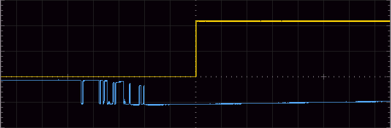
The trace below shows a typical push-button input (blue) and the resulting debounced output (yellow). Note that input is 5v per division and is active-low whereas the output is 2v per division and is active-high. From testing I did not see any traces where the bouncing went being the rising edge of the output, but this may not be the case with other makes of buttons. In addition to debouncing a side-benefit is the output always being high or low as opposed to high or floating from using a push-switch directly.