Running PIC16F630 code with gpsim
15 July 2017This article is about my very first experience of Microchip PIC firmware writing, which for various reasons I developed it using the gpsim PIC emulator rather than actual hardware, the main one being that at time of writing hardware had not yet arrived. Here the PIC16F630 is assumed, but I know already that is likely not the best choice of PIC chip — I was looking for some samples on the cheap at the same time I was ordering in a chip programmer, and some Shenzhen-based reseller on Ebay popped up selling a 5-pack of this chip for £2.
I did try out Microchip's MPLAB X IDE, but in the absence of physical hardware the Linux PIC eco-system seemed much more helpful, and for simplicity I'll cover MPLAB in a separate write-up. Here the open-source SDCC C compiler will be used, although it does have some issues compared to the LPLAB C compiler.
SDCC & gputils tool-chain
For Linux (and therefore just about every other platform) there is SDCC (Small Device C Compiler) for writing PIC firmware in C, which in turn makes use of gputils which provides an assembler & linker for PIC chips. It is nowhere near as polished as GCC, and seems to be missing some features — most notably some#pragma directives — that one would normally expect to be present, but it is functional. One thing to keep in mind is that SDDM and MPLAB have differences that make it difficult to write firmware that is drop-in compilable on both platforms, most notably they have different top-level headers and they use different syntax for inline assembly code:
/* MPLAB X */ asm("SLEEP"); /* SDDM */ __asm SLEEP __endasm; /* Semicolon is required..*/
As a result if you want a program to compile unchanged with both SDDM and MPLAB you will likley have to use a lot of #ifdef conditionals. Not sure how many common instructions have wrappers, but just using the assembly instructions is probably easier as they are what the chipset specifications mention.
Gotchas of embedded programming
I have a background in computer architecture so the conceptual overheads related to microcontrollers are not an issue for me, but PIC programming for the first time presented a surprising number of device-specific gotchas in a short space of time. Below is an overview of what caught me out before I got a working embedded program. Expect to have to read large portions of the PIC16F630 specification.- Default function of pins
- Most people new to microcontroller programming are more than likley only interested in general-purpose digital IO (input/output) pins, but in the case of the PIC16F630 just about all of the pins have multiple functions, and the default is usually one of the special-purpose functions. As a result an early pit-fall is working out the boilerplate code needed to change the pin functions to general-purpose IO, as the configuration variable is expressed in terms of enabling/disabling the specialist function rather than the mode of a given pin.
- Non-orthogonal features
- The second pit-fall is that things are not orthogonal — for instance even though the (non-power) pins split into two groups of six and each group can be read or written as a six-bit integer, one of the pins (
RA2which is the 4th bit withinPORTA) can not be used for output. Also, functionality such as having state changes trigger an interrupt is only available for a sub-set of input pins. - Watchdog timer
- The idea of a watchdog in itself is quite good, as it provides a last line of defence against program faults. However since it is enabled by default you either have to add the watchdog keepalive pings to your program or explicitly disable watchdog timeouts, otherwise your program will keep on resetting. This caught me out as MPLAB X's simulator has the watchdog disabled by default, unlike gpsim which has it enabled.
- Accessing registers
- Registers that can be accessed from “user-space” will have global variables pre-defined within system headers, although it is not entirely clear how the appropriate header for a given chip-set is selected. One thing that contributes to early confusion is interchangability between registers and the bits they contain, as both can be addressed using distinct identifiers, and different snippets of example code will follow different conventions of which to use. For instance
GIE(global interrupt enable) can be set in many different ways:- INTCON = 0b1000000; INTCON<7> = 1 GIE = 1
- That is writing the register as whole, writing to a specified bit of thr register, and using the
GIEbit's own identifier. Incidentally there is also some slightly incorrect naming –INTCON(Interrupt Control Register), which despite its name also doubles up as an interrupt status register, as it contains both enable (i.e. control) and flag (i.e. status/result) bits.- Configuraton registers
- Some registers cannot be accessed via pre-defined identifiers, as they reside in the special configuration memory space which can only be accessed during chipset programming (i.e. flashing) These correspond to different chip-set modes, such as the function of individual pins and how the chip is clocked, that cannot be changed dynamically. Naturally I found this out the hard way. These are the ones that are supposed to be set via
#pragma configdirectives, and the tool-chain fixes everything up. Unfortunately SSDC doesn't implement the#pragma configdirectives for the PIC16F630, so instead the register has to be set manually by specifying a variable with an address that corresponds to the register's location and then initialising it.
Some sample code
The following code is intended to drive two LEDs — one that blinks continuously, and one that turns on and off in response to a button press on an input pin. It makes use of an interrupt handler rather than polling to get input pin status.basic.c
#include "pic16f630.h" __code short __at (_CONFIG) cfg0 = _FOSC_INTRCIO & _WDT_OFF & _PWRTE_OFF & _CP_OFF & _CPD_OFF; void delay(void) { unsigned short iDelay; for(iDelay=0; iDelay<300; iDelay++) { __asm nop __endasm; } } void main(void) { CMCON = 0b111; TRISC=0; TRISA = 0b000101; IOCA= 0b11111; GIE=1; RAIF=0; RAIE=1; while(1) { PORTC = PORTC | 2; delay(); PORTC = PORTC ^ 2; delay(); } } void intr(void) __interrupt { unsigned char valInput; if(RAIF) { valInput = PORTA; if(valInput) PORTC = PORTC | 4; else PORTC = PORTC & ~4; RAIF=0; } }
This can be compiled using sdcc --use-non-free -mpic14 -p16f630 basic.c although it will throw out a few warnings about page selections and relocations — I'm not sure how important these are but so far I have not worked out how to suppress them. This will create several files, but the ones of interest will be basic.hex and basic.cod as they are the compiled firmware.
Running the code in gpsim
The easiest thing to do is to openbasic.cod in gpsim, as unlike basic.hex it includes information on the chipset the code was compiled for, saving the need to manually select it. I followed this tutorial on using gpsim's breadboard, and in practice the main things to get one's head around is the use of double-clicks rather than having an “OK” button and the horrible choice of terminology — a module is really a component, a node is really a wire, and a stimulus is really a connection to a wire.
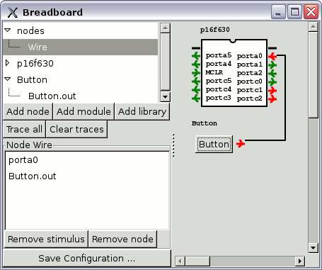
The nice thing about gpsim is that for each pin it shows both the pin's function and whether it is operating as input or output, and having this state exposed is a great help when running one's first program. At such an early stage even the most basic things are not obvious, and in my case it is how I found out that porta3/MCLR can only operate as an input pin.