Wireless counting buttons
14 March 2019Back at university the Real Ale Society, which was a student chapter of CAMRA, would hold an annual event in the students' union that non-members were invited to. Each keg of ale (and being Bristol each barrel of craft cider) had a button next to it that was supposed to be pressed every time a drink was served — this was used to update a projector display that showed how much of each drink was left. In practice it did not work quite as well as expected so the display needed some manual updating but the idea itself was sound. The aim of this project was to create a prototype wireless version of this system: A transmission board with buttons, and a base-station that would collate all the press counts.
Technically the project is a crash-course in wireless transmissions using RF (radio frequency) modules, and when I first started back around (I think) last November it was from a literal square one — I had some basic knowledge of electro-magnetics from Physics classes but I had no practical experience with RF circuits or their design. In the process I made my own RF modules, but decided to cover them in a separate article.
Bootstrap circuits
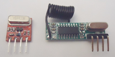
Since I did not have access to an oscilloscope or any RF measuring equipment the starting point is off-the-shelf RF transmit and receive modules to create working reference circuits that can be built upon, so I opted for the RF SolutionsQAM-TX2-433 and QAM-RX10-433 modules (Farnell 2500107 & 2759280 respectively) which are both shown below. The data-in pin of the transmitter (left) switches a carrier signal on and off, and the data-out pin of the receiver indicates whether a carrier is detected or not — this is about as simple as these things can be, and require just a single micro-controller GPIO pin. Host prototype boards were made that utilise these modules, and they are detailed in the next sub-sections.
Prototype transmission board
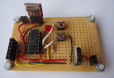
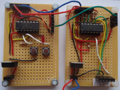
The transmitter board consists of two trigger buttons and aPIC16F630 that outputs a signal encoding a data-frame to the data-in pin of the QAM-TX2-433 — the latter module being plugged into the board at the top-left of the image below. Idea is that the transmitter board would keep local count of how often each of the buttons had been pressed, and when a press occurs it would transmit the press counts — the details of the data-frame containing the values are covered later. The PIC16F630 was used as the controller because this is one of the few situations where these chips are of any real use — all that is needed is some GPIO and timing ability. To be fair the chip itself does not have the complexity that the other PIC chips I use have, and is pretty robust with a wide range of operating voltages.
The transmission firmware was not particularly complex compared to other firmwares I wrote around the same time, such as the prototype LCD-based timer. Its ultimate purpose was to emit a test frame upon the press of a button, thus provide something for which a receiver circuit and firmware can be built upon. Most of the complexity is in the code to do debouncing, which is an assembly version of the algorithm I think was first used in a PIC16F88-based LED timer — the transmission of a frame itself is done via pin toggling separated by blocking use of Timer1 which is pretty much the most expedient way of generating a wave-form for the RF module. The transmission firmware is in the single file txunit.asm.
Prototype reception board
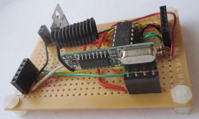
The reception board uses aPIC16F1823 which reads the data-out pin of the QAM-RX10-433 which is plugged in at the front of the board. Although there is provision for communication via both I2C and RS232, only RS232 is used for outputting decoded frame data — or rather as was the case for most of the development time, debug information — to a PC for processing. The PIC16F1823 is used because the PIC12F18xx/PIC16F182x family of PIC microcontrollers are my go-to ones these days, due to the communication features they have, and in hindsight for logistical reasons I probably should have used the chip for the transmitter as well.
Compared to writing the transmission firmware the code for the prototype transmission board was an ordeal to develop, and at one point had given up on it in favour of using an ARM microcontroller. To measure the duration of and between pulses the Capture/Compare/PWM unit of the PIC16F1823 is used in capture mode, which takes a snapshot of the time value of Timer1 when the expected transition occurs. For some reason the capture-compare unit can detect either a rising or falling edge, but not both at the same time, so after each rising or falling edge the unit has to be reconfigured to detect the opposite edge type. Further details are in a later section on data-frame decoding.
Data-frame encoding
The data frame used for updates from the transmitter circuit consists of seven 8-bit fields and these are summerised in the table below — the individual fields are described in the subsequent sub-sections. Frame data is encoded using Manchester coding which guarantees that each transmitted bit results in a high-low or low-high transition, and hence imposes a tight limit on how long the carrier signal can be switched off for, so that it is possible to distinguish between long runs of zero bits and the absence of a transmission. It is far from the most efficent way of avoiding long runs of zeros making transmissions go quiet, but it is a relatively simple off-the-shelf algorithm. The data frame used for updates from the transmitter circuit consists of seven 8-bit fields and these are summerised in the table below — the individual fields are described in the subsequent sub-sections.
| Header | Payload | Check | ||||
| Prefix | Length | Node Id | Button 1 count | Button 2 count | Transaction count | |
Transmission prefix
The AGC (automatic gain control) of the RF receiver continually adjusts amplification of the received signal based on its strength, but in the absence of a transmission the amplification is increased to a point that it is just reading noise, resulting in random received data. A transmission prefix consisting of equally-spaced highs and lows causes the AGC to adjust itself to an appropriate amplification level, and the detection of a consistent pattern rather than random values on the output data is used to detect the start of a transmission. The value0xfe, which results in the wave-form shown below, is used because it allows both the prefix and the rest of the data frame to use the same Manchester coding logic.
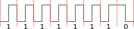
There are six equally-spaced highs of the same widths, which is ample for the signal to be locked onto and a transmission bit-rate derived from the spacings. The final high of double width is used to indicate the end of the prefix, as an unknown number of the prior peaks will be incorrectly received while the AGC adjusts. Lastly the prefix starts and finishes on a signal low.
Length header
The number of bytes (i.e. fields) in the remainder of the packet including the check byte — inclusion of the latter is to simplify decoder implementation, as covered below. For this project the length header is a fixed value of five, but I plan to use the same frame format with larger arbitrary data payloads, hence its inclusion.Packet payload
In order to simplify the firmware and keep the frame format as general as possible, all other information within the frame is considered part of the data payload, and apart from the check byte is treated as application data to be passed on.- Node ID
- The node identity is used to indicate which transmitter is updating its counters. This would normally be a header in its own right but for these circuits addressing has been delegated to a higher communication layer.
- Button 1 & 2 counts
- Individual nodes maintain their own count of button presses so that a lost transmission does not result in the receiving end having a perpetually incorrect count — an important thing given the open-loop nature of the transmissions. Some extra logic is needed in instances where a button will be pressed a total of more than 255 times, which implicitly assumes that there will also only be so many transmission failures between button presses.
- Transaction count
- In practice a counter that is incremented when either of the buttons is pressed — included so that there is a bit more information available for handling lost transmissions.
- Check byte
- The exclusive-or sum of the other fields, excluding the prefix. Intended as a very basic error detection check, and if the value calculated by the receiver side differs from the transmitted value, the whole frame is discarded.
Data-frame decoding
The decoding procedure is based around tracking the time between toggles of the data output line from the RF module, although one challenge was how to implement allowance for jitter given limitations of the PIC instruction set and 8-bit register widths. With Manchester coding the interval between two edges is either “short” or “long” where the latter is twice the duration of the former — the receiver firmware was setup so that would notionally have durations of 200 and 100 tics respectively which precludes any form of summation within the algorithms. This section covers just the algorithms, with firmware implementation issues discussed separately.Transmission prefix detection
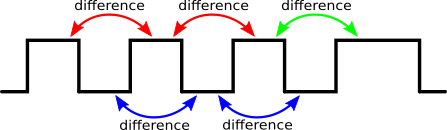
Detection of the transmission prefix is done by calculating the difference between the most recent pulse marks (signal high duration) and pulse spaces (signal low duration), as shown in the figure below. If the difference between the first three marks (shown in red) and the two spaces (blue) are less than five tics, the penultimate mark is compared (green) with half of the final mark — if this difference is also less than ten, a prefix has been detected. The noise from quiet conditions is very unlikely to meet these tolerances.
To show the algorithm in practice actual values obtained from a test-run are shown in the figure below — the dotted red box indicates part of the incoming signal that is clearly just noise, and the blue dotted box indicates which part of the signal was being checked when the prefix was detected. In this case the first two highs are sufficient for the signal to stabilise to reasonably tight values, although in total three are given over for the AGB to settle. There is clearly scope for tweaking, such as the number of marks/spaces to check and the tolerance, as the results shown are for a specific receiver in specific conditions.

Note that the widths of the marks and spaces coverge onto values that are not equal — this is discussed later and is something that caught me out — for now it will suffice to say that the marks and spaces have to be handled seperately for the prefix detection. For data decoding the gap threshold between a short and long gap will be 150% of the short gap, which in this example will be 104+104>>1=156.
Header & payload decoding
In terms of decoding the header and payload are logistically the same, and that is a multiple of eight Manchester-encoded bits using references widths extracted from the transmission prefix. Normally Manchester code is supposed to be clocked, but the implementation here will instead just consider whether any given gap between rising/falling edges is above or below a threshold. Firstly consider the two simple cases of a “long” gap:
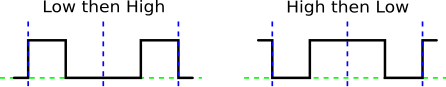
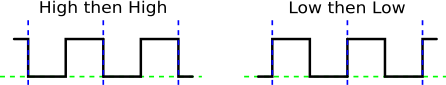
A rising edge after a long space is always a binary one and a falling edge after a long peak is always a binary zero — if this is not the case decoding has screwed up. However in the case of short gaps as shown below, a check needs to be done to see whether the edge is actual data encoding (between dotted blue lines) or simply the signal toggling (on a blue line), as in the latter case the edge is disregarded.
The algorithm actions are summerised in the table below, where lastEdge is a single bit of status that indicates whether the last rising or falling edge was disregarded.
The gap width begtween edges will be considered either short or long — single- or double-width in other words — depending on whether it is above or below the gap threshold calculated during prefix detection.
| Gap width | Edge type | lastEdge value |
Status action | Data output |
| Long | Rising | don't care | lastEdge=0 |
1 |
| Long | Falling | don't care | lastEdge=0 |
0 |
| Short | Rising | 0 | lastEdge=1 |
no action |
| Short | Falling | 0 | lastEdge=1 |
no action |
| Short | Rising | 1 | lastEdge=0 |
1 |
| Short | Falling | 1 | lastEdge=0 |
0 |
Edge-detection vs. sampling
Although in this circuit I used output from the microcontroller's edge detection, which in turn is reliant on filtering (if any) done by the receiver module, and I have doubts about its potential robustness in marginal conditions. A more robust approach would instead be to sample the entire expected symbol width, and based upon those samples decide whether the symbol has a rising or falling edge in the middle. The main advantage of this is that it does not matter if the falling edge is ill-defined or even if it bounces around a bit during transition, but it places a higher computational demand on the microcontroller and the firmware doing the decoding, particularly if some extra filtering is done in software. For now I do not know the relative merits of this approach, in particular since the problems it solves may be better alleviated via hardware filtering.Wave-form skewing
As
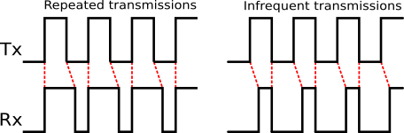
I am not sure what causes these effects but to me it looks like inductance within the wireless channel, although I suspect that it may in turn be caused by energy still stored in capacitors within the RF circuitry. As a quick sanity check I removed the transmitter and receiver modules and wired the transmitter and receiver boards together directly as shown below, with the data output of the transmitter microcontroller going straight into the data input of the receiver microcontroller. In this case there was no difference between mark and space widths, which verifies that it is an artefact of the RF channel.
So far I have assumed that once the mark and space values have been settled upon, they remain constant throughout the transmission, but I suspect that this assumption is unsafe for all but the shortest transmitted frames. I suspect that for longer frames thresholds may require dynamic adjustment.
Firmware implementation issues
The bootstrap circuits themselves are fairly straight-forward, both being completed sometime last year, with all the complexity being in the firmware. The sections below covering various issues encountered during development of this code, most of which are related to the decision to write the firmwares entirely in assembly. The firmware used for both the prototype transmission and reception boards is available within my Bitbucket repository.Giving up on C
Although not explicit in the previous article on pure vs. inline assembly, at the time I wrote it I was on the verge of giving up using C for PIC microcontroller programming. C compiled to PIC has pretty poor performance, which I was getting around by using more and more inline assembly, and for many bit-orientated operations PIC assembly was actually easier to use than C. However writing firmware entirely in assembly is a different world and making that jump was harder than expected — it requires an entirely different way of thinking about problems. However it also unlocks a lot of advantages and at least for anything timing-critical I doubt I will ever look back.Limited variable range
Although capture mode has a resolution of 16 bits, registers on the PIC microcontroller are only 8 bits wide, and doing 16-bit calculations is a right pain involving the use of carry/borrow bits set by instructions. As a result only 8 bits are used for timing purposes, and the entire range of values is given over to the expected intervals of the transmission coding — this means there is not enough range to do things like summation and hence calculate things like averages. This is why the transmission prefix detection is based around checking the difference between pulse widths rather than calculating any jitter values. While the extra hoops to jump through to get 16 (or more) bits on an 8-bit system can be dealt with, it is one of those things that makes me wonder whether I am better off using a different chipset that natively supports wider integers.Use of macros
For programming tasks such as the DSP done by the reception firmware, one has to think in terms of constructs that are higher-level than the instructions within the PIC architecture, and that means using macros. For example detection of the transmission prefix is based around checking differences, and uses the following macro:IfDiffOverL macro valA,valB,valLimit local noborrow MOVFW valA SUBWF valB,0 BTFSC STATUS,0 ; Skip if W bigger (was borrow) GOTO noborrow MOVFW valB SUBWF valA,0 noborrow ; W = abs( diff(A,B) ) SUBLW valLimit BTFSS STATUS,0 ; Skipped if diff(A,B) <= limit ENDM
In PIC assembly comparisons are done by doing a subtraction and then using the status bits as part of a conditional branch. If the subtraction done to calculate the difference results in a borrow, it is repeated with the two variables swapped; in either case the result is then compared with the threshold using a further subtraction. However since conditional branches are limited to skipping over a single instruction, the latter instruction is usually itself a branch (i.e. GOTO). Throw in various negations such as the carry bit also being “no borrow” and it is easy to lose track of which code paths should correspond to ‘true’ and ‘false’. The macro wraps up the complexity — macros are something I found by accident and my only regret was not finding out about them earlier.
Use of multiple microcontrollers
One of the issues using different microcontrollers in the same electronics project is that the MPLAB flashing program needs to download a new firmware to the PIC-Kit programmer device every time the target chipset is changed. For this project the transmitter firmware did not change very often so this was not a major problem in practice and in some cases it actually prevented me from flashing the wrong firmware to the receiver controller, but switching between flashing of the two firmwares was often enough during critical debugging to be annoying. Like thePIC16F88 I am phasing out use of the PIC16F680 but it will be a few more projects before my stock of the latter is finally used up.