RS232 LCD display rework
09 July 2018Late last year I made a RS232-controlled LCD display, although at the time there were faults which at the time decided not to fix because the ambition behind the project had mostly been satisfied. Over the weekend I decided to have another look at the board, and as it turned out it was not much effort to get it working as originally intended.
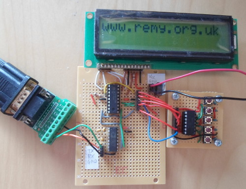
The picture above shows the button header wired up to a debouncing circuit, although at the time I did not regard electrical bouncing as a major problem with the circuit. The debounce circuit also always outputs a definite high or low, so I don't have to concern myself about floating inputs.
Background
Unlike my other circuits, this project has a history behind it — it is a black-box recreation of an in-house display & control module I spent a lot of time interfacing with back in 2011-2012. When I got back from New Zealand in 2013 one of the things I tried doing was driving an LCD display similar to the ones I had used previously, but did not successfully manage to do so. It was when revisiting the challenge in the summer of 2017 that I managed to successfully drive an LCD display, and then used making a timer as a context for refining the firmware code into something useful. Porting the LCD control fromPIC16F630 to PIC16F88 and creating an RS232-controlled display would result in a mile-stone circuit that is one of the ones I still keep on my desk.
The faults
The only hardware fault with the circuit was a short bridge between pins 11 and 12 —RB5/TX and RB6/PGC — which I only found almost by luck. I was checking for broken connections with a multi-meter and found the short, which is shown below under magnification, between the pin I was interested in and the one next to it. A quick sweep with a hot soldering iron was enough to remove it.
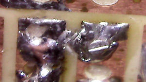
Given that there were other faults with the circuit at the time that I did manage to rectify, I probably was not in the mind-set to go hunting for the actual problem, and just wanted to “finish” the project. Pity really as this short was the cause behind most of the accepted defects with the circuit.
In-circuit flashing fault
At the time I noted that in-circuit programming stopped working when I installed the RS232 driver chip, and I a guessing this is when the short was introduced. While I was sort of correct in concluding at the time it was due to electrical issues, it was most likely due to the clock line being connected to another pin that to my knowledge had an internal pull-up enabled, rather than issues with the driver itself. With the short removed, in-circuit flashing worked perfectly:
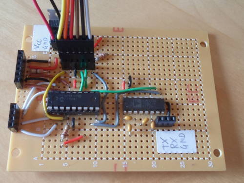
As an aside, flashing worked even though the whole circuit was powered up, including the LCD display. A lot of the circuit I made since then that required microcontroller flashing were ones using a PIC12F1822 where I basically had to remove the chip in order to flash it, but not being able to get in-circuit flashing working at the time made my somewhat adverse to using it.
Faulty buttons
When the chip programmer was not attached to the header, the header was used to connect buttons, but only the button attached toRB7 seemed to work properly. Since RB6 was shorted together with the inbound RS232 line random toggling was a problem with the input, and like the problems with flashing removing this short solved this issue as well. The third input button RB3 did not work at all, but this was because low-voltage programming was enabled, which disables I/O on RB3.
Firmware improvements
Although indications are I did not try to useRA5/MCLR as a fourth button input, in part due to it being on different port to the other pins used for buttons, it would not have worked as disabling of MCLR is ineffective unless low-voltage programming is also disabled. Aware of this pit-fall from subsequent projects I was able to fairly easily have four operational buttons, which is what the original inspiration for this circuit had. The other change was to get writing to the second line working properly:
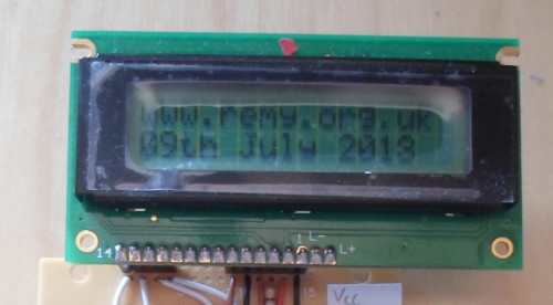
If enough characters were typed off the end of the first line then text would eventually start appearing on the second, but the right way to do this was to explicitly set the caret to DRAM address 0x40, which corresponds to the start of the second line. It was a simple enough thing to work out how to do in isolation, but at the time I was chasing multiple other issues and did not consider this a priority. I did some other changes & cleanups to the firmware, which rather than being included in this article has been placed into my Bitbucket pic-code repository.
Conclusion
I have mixed feelings about reworking this circuit, which only re-visited because I had been building another that made use of in-circuit flashing. On balance I think deciding to bring the project to a conclusion rather than fix the defects was the right decision, because the knowledge needed to fix things such as the non-operational buttons would take a lot of time & anguish on subsequent circuits to work out. Nevertheless the sheer speed I fixed all the faults makes me wonder why I did not try doing so earlier. In any case it is one more firmware mini-project I have migrated to my Bitbucket repository.If at the time I had got the circuit into the operational state it is now at, it is reasonably likley I would have made a PCB version, and almost certainly would have gone on to mount the curcuit & display in a project box. Instead this is something I did with an LED-based timer a few months later. I have all the parts such as D-sub connectors in stock, so might well go ahead with the project.