Driving DEM16217 LCD display
18 August 2017Here is a write-up of writing the firmware to drive a 2-line DEM16217 LCD display, running both under emulation and on a PIC16F630 attached to a physical unit. It was frustrating at first, but I eventually managed to get something displayed, and it seems simple once you are no longer in headless-chicken mode trying to get it to work. The PIC16F630 is assumed, as it is simpler to configure than the PIC16F88.
Background
There is some history with this project, as it is in part a long-standing ambition. Shortly after getting back from New Zealand I got myself a Franzis Arudino kit, most likely from Maplin during one of my shuttle-stop weekend back in the UK. For reasons I have long forgotten I didn't get very far with it and I diverted my attentions to more immediate concerns, but what I do remember is wanting to program the Arduino board to drive an LCD display, which was pretty much a recreation of some custom-built server control panels I used in my then-previous job. I suspect the idea of the project was due to being denied any opportunity to do any embedded (i.e. non-x86) programming at this company.Spin forward a few years this same project was the thing that sprung to mind having ordered a Raspberry Pi, but I ended up doing it using Microchip PIC controllers instead, mainly because the Linux PIC eco-system proved surprisingly helpful. To some extent RaspberryPi does not really feel like a proper embedded system, and for this project would probably would have introduced unnecessary complications. This is all part of a semi-serious attempt at getting some hands-on experience in what today falls under the Internet of Things marketing umbrella.
gpsim support
As it happens gpsim includes a module that emulates an LCD based around the HD44780 controller, which coincidentally is also the controller the DEM16217 LCD package I had got a few years previously uses. This was good because at time of writing my PIC flashing tool had yet to arrive, and in any case using an emulator means not having to worry so much about electrical issues which you get the protocol right. In part this is perhaps lack of experience interpreting electrical datasheets.
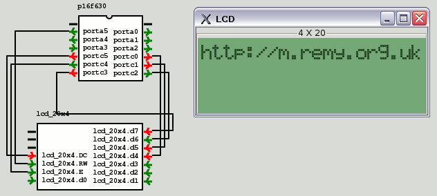
At least in gpsim v0.90.0 the 2-line LCD module (2 x 20) seems to really be a 1-line module, and the 4-line module (4 x 20) only gives two working lines. I have not investigated whether this is a bug, or whether it is a mistake on my part due to using incomplete specifications as reference.
Sample code
This is an almost direct implementation of the flow chart in Section 11-2 (PDF page 15) of the DEM16217 datasheet and is pretty minimalist, but it is enough to get something displayed. There's more than one version of the datasheet out there and I have no idea of this one is official, but the information it contains seems to be correct. When I was working this out first time round I used 8-bit mode, but here I will use 4-bit mode as it means less wiring.lcd4.c
#define NO_BIT_DEFINES #include "pic16f630.h" __code short __at (_CONFIG) cfg0 = _FOSC_INTRCIO & _WDT_OFF & _MCLRE_OFF & _PWRTE_OFF & _CP_OFF & _CPD_OFF; void pulsedelay(void) { // For actual hardware, this will need to last 1ms, which at // 4MHz is ~2000 cycles.. unsigned short count; for(count=0; count<2000; count++) { __asm nop __endasm; } } void lcdBangNibble(unsigned char bits) { PORTC=0b010000 | bits; pulsedelay(); PORTC=0b000000 | bits; pulsedelay(); } void lcdWrite4(unsigned char letter) { unsigned char lo = letter & 0b1111; unsigned char hi = letter >> 4; PORTC=0b110000 | hi; pulsedelay(); PORTC=0b100000 | hi; pulsedelay(); PORTC=0b110000 | lo; pulsedelay(); PORTC=0b100000 | lo; pulsedelay(); } void lcdWriteStr(unsigned char *str, unsigned short len) { unsigned short idx = 0; while( idx < len ) { lcdWrite4(str[idx]); idx++; } } void main(void) { // Get pins into right mode CMCON = 0b111; TRISC=0; TRISA=0; // Set to 4-bit mode lcdBangNibble(0b0010); lcdBangNibble(0b0010); lcdBangNibble(0b0000); // Display on lcdBangNibble(0b0000); lcdBangNibble(0b1111); // Clear lcdBangNibble(0b0000); lcdBangNibble(0b0001); // Entry mode lcdBangNibble(0b0000); lcdBangNibble(0b0110); // Write something lcdWriteStr("http://m.remy.org.uk",20); // A loop while(1) { __asm CLRWDT __endasm; } }
Running on physical hardware
Of course the real test is driving an actual LCD module rather than a virtual one, as the whole point of firmware programming is to drive physical electrical circuits rather than just being a purely software-based exercise, and below is the result. It turned out to be much more difficult than I expected to go from working firmware to complete operational hardware, but for me seeing this run was a long-standing ambition:
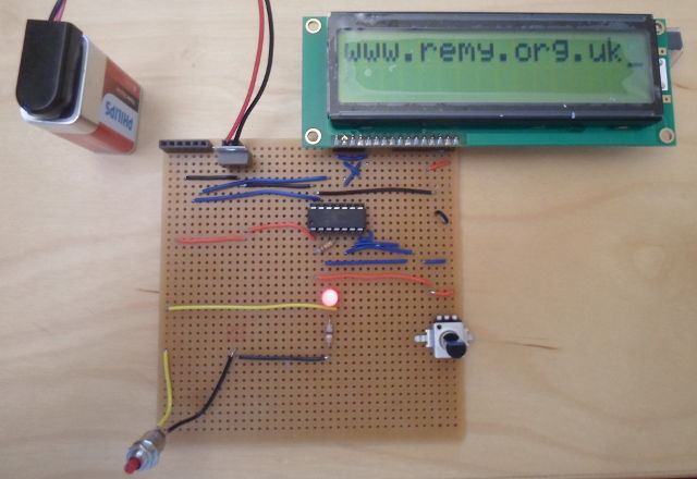
The circuit board was designed with self-sufficiency and debuggability in mind — it has its own power regulator, in-circuit programming, a reset button, an IC socket so that the microcontroller can be replaced, and an LED that allows firmware to show output without relying on the LCD module. I originally tried building a simpler circuit on solder-less breadboard, but among other problems I am pretty sure that incorrect use of the PICKIT programmer and/or the chip seat fried at least two of my stock of PIC16F630 chips — and I was pretty much expecting as much — which was one of many motivations for this complication-eliminating design.
The firmware used to create the images above — especially for the physical circuit — is somewhat temperamental, and I have yet to put time into writing a much more solid code-base. In particular there is overkill in delay loops rather than checking busy status, and startup LCD resetting is nowhere as exhaustive as it ought to be. Sometimes when a battery is connected (or more usually, re-connected) the LCD display does not show what is expected. Another unresolved complication is that gpsim has 20-character displays, whereas the actual hardware units at 17-character, and at time of writing have not tested two-line writing with physical modules. But for now I am happy.