Counter-comparitor signalling
01 July 2018In the past I have thought about using a single clock line to signal the round-robin activation of LED chips within numeric LED display circuits, and have finally decided to build a proof-of-concept circuit that implements such an approach using binary counters. This is something I first speculated on as an alternative to I2C I/O expanders, but only recently found suitable components at a reasonable price. A comparator is used to decide when the count corresponds to when the respective LED chip should be activated.
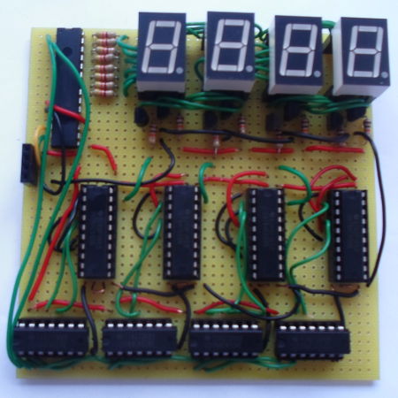
The proof-of-concept circuit uses Multicomp 8-segment LS0565SRWK LED chips purely because they required the least wiring out of all the suitable LED chips I had in stock — I would not use this approach for LED matrices which have a high proportion of ground pins.
Architecture
While it is possible for each LED chip to be individually wired, it is logistically simpler to have all the corresponding display segments wired together, and pulse each chip in turn — this approach relies on sufficiently fast blinking being imperceptible from continuous power, and is an adaptation of the architecture used for the LED matrix display. Since the LED chips are activated in a fixed order, an alternative is to have a single clock line from the main controller and delegate the round-robin activation to circuitry next to the LED chips. This approach is shown in the circuit diagram below.

The counting is done by a SN74HC161, and a SN74HC688 comparator is used to trigger the LED sinking transistor when the appropriate count value is reached. Although not strictly required when the number of LED chips is a power-of-two, in practice the counter resets will also be wired up so that the main controller is able to force a known counter state, rather then assuming fixed start-up values. A prototype of the activation circuitry for each LED chip is shown in the picture below.
Current sink switch
Because the comparator output is high when its inputs are not equal, this output needs to be inverted in order to obtain a logical high when the counter is at the trigger value. A pair of NPN transistors are wired so that they sink load current when the input is low, as shown in the circuit schematic below:

I ordered in some SN74AHC05 hex inverters which had the notional advantage of open-drain output (rated at 8mA per pin) allowing them to be attached directly to the LED chip ground pins, but these inverters were active-low output and hence sank current when presented with a high input.
Resistor ratings
Although previous brightness experimentation used 18-segment KingbrightPSC05-11CGKWA chips, they seem to have similar power specifications so I used the results as a starting-point. Because of the higher duty-cycle — 25% here whereas the experiments used 10% — I settled on using 4.3kΩ resistors rather than 1-2kΩ. Each lit segment will consume around 0.75mA, for a potential maximum chip draw of 6mA.
The transistors have a gain of 200 so supplying 6mA requires a base current of 0.03mA, and as a result could have got away with using 78.8kΩ (would give about 13mA) for Rsink, which is the largest resistor value I have in stock. However when I was building the circuit I was not really interested in fine-tuning power parameters, so instead opted for some of my usual 10kΩ resistors instead. For simplicity I decided to use the same value for both transistors, even though Rin could have been as high as 2MΩ.
Control chip
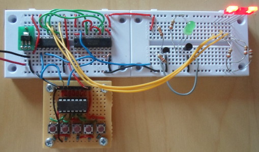
For this circuit I wanted to avoid writing firmware, because doing so would be tangential to the core proof-of-concept of the counter-comparator sub-circuits. Therefore I decided to use anMCP23017 I/O expander as the control chip, which happened to be the only through-hole 16-bit expander I had in stock, and actual control coordination being done via a script running on a PC.
Power supply
Since the USB-ISS I2C adapter is capable of supplying upto 80mA, which is a lot more than I planned to use, I decided to dispense with having a dedicated power supply and draw all the power from the USB adapter. Many of my past circuits have either been generous with the required current draw, or simply not paid any attention to it at all, but as with the Cypress expander experimentation I concluded that just using the USB adapter for power made things easier.Building the circuit
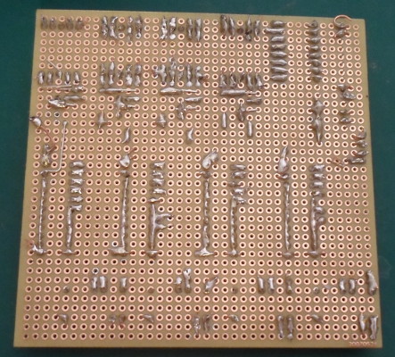
For this circuit the components were mounted onMC001796 (Farnell 2770324) 38x38 hole matrix board, which is perfboard under another name, with connections using combination of solid AWG23 and multi-strand wire. The underside of the complete board is shown below, showing all the solder connections, and follows is some various remarks regarding the construction process.
Fritzing
Although I long stopped using Fritzing for PCB design, I still use it for roughing out through-hole circuits on prototyping breadboard, and this circuit was no exception. However while Fritzing does a reasonable job with strip-board and phenolic prototyping board it does not work with the much more ad-hoc perfboard — using wires to represent the bridging on the underside of the board is a bit of a pain, and issues with bending wires around pins mean it is much more prone to needing changes. The underlying problem is modelling perfboard as single-sided, which works with strip-board because aside from the tracks there are no connections on the solder side. However Fritzing still has other annoyances it really ought not to, the major one for this circuit is the transistors using a backward leaning parallel-projection rather than a top-down one like most of the other components:
![]()
![]()
The pictures above shows the transistor layout for the LED chip drain mini-circuit, both how it appears in Fritzing and how it appears on the physical prototyping board. The way transistors are drawn makes it hard to see connections behind the transistor, so is almost useless for laying out transistors in close proximity.
Pros & cons of perfboard
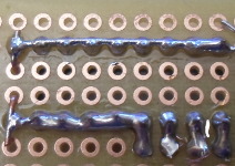
Ideally this project should have used prototyping board optimised for integrated circuits, but theMC01010 phenolic prototyping board I often use simply wasn't big enough to fit everything in. Pretty much every aspect of using perfboard was a mixed blessing. The integrated circuits required a lot of pins to be tied to Vcc or ground, and the lack of any power tracks meant the headache of having to add a lot of wires just to route power. On the other hand the comparator chips only used two of the eight comparison pairs, so was able to ground a lot of the pins by simply laying down strips of solder, as shown below.
Chips could be placed at different orientations, but this was done for reasons of space and at times was a source of confusion. The hardest thing with using perfboard was that many pins, most notably those on the headers for the LED chips to be plugged into, had to have more than one wire connected to them. The multi-strand wire tended to fray so care was needed to avoid shorts, whereas bending the solid-core wire into place often caused the IC socket pins to get flattened. In hindsight I probably should stock a thinner solid-core wire.
Choice of wire
I have a much greater preference for solid-core wire over multi-stand wire, because loose strands of the latter cause all sorts of pain, but the AWG23 solid-core wire I had in stock is a pain to bend into place. AWG23 was a good choice for other types of prototyping board where a relatively stiff wire was easy to keep in place prior to being soldered, but with perfboard the flexibility is much more crucial. When soldering several wires together, the combined heat capacity of AWG23 wires means it is a while before the solder starts sticking to the copper. Prior to it going into administration, wire was one of those things that I bought from Maplin so I knew what I was gettingIndependent component sets
Somewhat dogmatically each comparator had its own counter, and used four separate LED chips rather than a 4-in-one chip such as theCA56-12SEKWA (Farnell 2478712). While these were in keeping with the original proof-of-concept, it also results in a circuit much more complex than its functionality requires. Wiring up the parallel segment connections for the LED chips was particularly troublesome, and in the past I would have simply ordered in a mini-PCB instead.
Operation
To test the circuit it is hooked up using the ISS USB adapter, which in turn is controlled using the usual Python test script. Since all three address pins are tied high, the I/O expander's I2C address will be0x4e. First off some setup is required, consisting of setting up the USB adapter, and then setting all pins to output:
./ttyTxRx.py /dev/ttyACM0 2 5a 02 70 0 ./ttyTxRx.py /dev/ttyACM0 1 55 4e 00 1 00 ./ttyTxRx.py /dev/ttyACM0 1 55 4e 01 1 00
The segment pins are attached to Port B, and for simplicity the following will assert all eight of the pins on this port (i.e. lighting all segments):
./ttyTxRx.py /dev/ttyACM0 1 55 4e 12 1 ff
The clock and reset lines are connected to Port A. Counter increments occur on the falling edge, so to send a clock assert Pin 0, wait a short while, and then clear it. Doing this shoud cause the LED chip that is lit to change:
./ttyTxRx.py /dev/ttyACM0 1 55 4e 13 1 1 sleep 1 ./ttyTxRx.py /dev/ttyACM0 1 55 4e 13 1 0
..and finally, to send a reset assert then clear Pin 1:
./ttyTxRx.py /dev/ttyACM0 1 55 40 13 1 2 sleep 1 ./ttyTxRx.py /dev/ttyACM0 1 55 40 13 1 0
Practicality
While functional, the approach has several deficiencies. From my perspective by far the biggest problem is that each counter-comparator mini-circuit needs to have its “address” hard-wired, and as a rule such per-unit customisations spell trouble for logistics — at the very least care has to be taken not to mix up all the otherwise-identical mini-circuits, and if the latter were mounted on daughter PCBs alongside the LED chips, they could not be swapped around. Before I found the off-the-shelf counter & comparator chips I had long ago considered implementing counter-comparator logic in micro-contollers, but considered the need to flash slightly different firmware to each one to be asking for trouble.In practically all scenarios better use of per-LED counters would be to cycle the segments rather than whole LED chips, which has the immediate advantage of also not needing any per-LED customisations. For a small circuit like this one it would actually result in a bigger saving of wires needed from the main controller, and the decoder chip to fan out the counter output would also be smaller — so far I have not found a counter that directly outputs decoded signals. For very large numbers of LED chips, where using counter-comparators to activate LED chips would save a lot of wires, the effective LED duty-cycles might end up too low and setup logistics as mentioned above become a real headache.
On the plus side I think there is nothing inherently wrong with the approach, and that much of the disadvantage is because the components best suited for such hard-wired techniques belong to a different era. The more general idea of moving control logic away from the main controller onto — ideally hard-wired — auxilliary sub-circuits is fundamentally sound, and this is the first actual attempt I've made of doing such off-loading.
Concluding remarks
As is often the case more recently, this circuit was more about process than outcome, in particular the trying out of not only just new components but also a new prototyping board. Making a basic NOT-gate from a transistor in itself was nothing significant, but it is not often that I resort to combining discrete components. Although electrical parameters were not any real concern with this circuit, the assumptions about brightness were wrong and when pulsed the LED chips were noticeably dim, which is at least an indication i should look closer at brightness issues. Then again it is possible that the poor luminisity — something to be investigated.In the near future I will be looking at wire-reducing breakout boards for the 17-segment LED chips, and there are one or two things I found out while making this circuit that are relevant to this next project. Ideally I would prefer projects that are not centred around LEDs, but that is the way things seem to go in practice.