TM1668-driven LED displays
18 July 2026Having written my own firmware for the Titan Microelectronics
TM1637 LED controller that drives the off-the-shelf time display used in the most recent timer project it seemed a good idea to try some of the other chips within the same apparent controller family, so ordered in units of the TM1620 and TM1668 for experimentation of which the latter is described here.
Of all the variants I am aware of and certainly among the three I have personally tried the TM1668 is by far the most functionally interesting chip within the family of LED controllers, although not sure of its practical usefulness in the foreseeable future.
TM1668 pin-out
The pin-out for the TM1668 as per the data-sheet is reproduced below. Segment pins 1–10 also double up as Keyscan pins 1–10 and Pins 17–19 are either segment or grid output depending on chip configuration. According to the data-sheet the serial pins have internal 13.3kΩ pull-up resistors so external pull-ups are not required. For unstated reasons segment pins have 7.2kΩ pull-downs and grid pins have 2.7kΩ pull-ups which is probably why some segments are sometimes faintly lit if wiring is incorrect.
| LED common | Ground | LED common | Configurable output | LED segments | |||||||
| Grid 1 | Grid 2 | Grid 3 | Grid 4 | Grid 5 Seg 14 |
Grid 6 Seg 13 |
Grid 7 Seg 12 |
Seg 10 | Seg 9 | Seg 8 | Seg 7 | |
| 24 | 23 | 22 | 21 | 20 | 19 | 18 | 17 | 16 | 15 | 14 | 13 |
| 1 | 2 | 3 | 4 | 5 | 6 | 7 | 8 | 9 | 10 | 11 | 12 |
| DIO | CLK | STB | K1 | K2 | Vcc | Seg 1 | Seg 2 | Seg 3 | Seg 4 | Seg 5 | Seg 6 |
| Serial interface | Key sense | LED segments (anode) | |||||||||
Experimentation using the circuit below showed that it is possible to use the STB as a chip-enable allowing multiple TM1668 chips to use the same serial clock and data lines, although the presence of internal pull-up resisitors may cause issues with serial signalling if several of them being daisy-chained.
Being able to configure pins as either current-sourcing segment or current-sinking grid means that it is possible to use either common-anode or common-cathode LED displays, although in this case of the common-anode 3642BS-1 the lack of an 8th grid means the colon is not available.
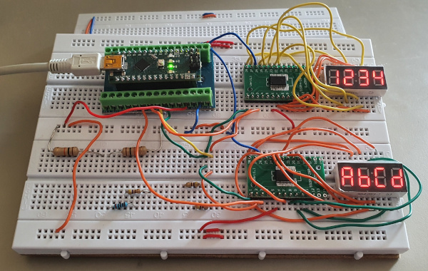
This circuit became a mini-project in extending my firmware to support displays wired up with the LED common pins being wired to the chip segment output rather than grid output, but aside from some debugging it was the conversion from the segment bits being in a single byte to being distributed over multiple bytes.
Control protocol commands
Below is a summary of the command bit-sequences that are supported by the TM1668 chip, which aside from differences in what each chip provides is basically the same across allTM16xx units.
Note that most of the functions such as pulse width and display enable are set in groups rather than individually, hence the blank cells within this table which is laid out similar to the source table in the data-sheet.
The test mode is not documented.
| Bit 7 | Bit 6 | Bit 5 | Bit 4 | Bit 3 | Bit 2 | Bit 1 | Bit 0 | Function |
| 0 | 0 | Unused (set to zero) | 0 | 0 | Use Seg 12–14 | |||
| 0 | 1 | Use Seg 12–13 & Grid 5 | ||||||
| 1 | 0 | Use Seg 12 & Grid 5–-6 | ||||||
| 1 | 1 | Use Grid 5–7 | ||||||
| 0 | 1 | Unused (set to zero) |
One of below | 0 | 0 | Write LED data | ||
| 1 | 0 | Read Keyscan data | ||||||
| 0 | Auto-increment | |||||||
| 1 | No auto-increment | |||||||
| 0 | Normal operation | |||||||
| 1 | Test mode on | |||||||
| 1 | 0 | Unused (set to zero) |
0 | 0 | 0 | Set pulse width 1/16 | ||
| 0 | 0 | 1 | Set pulse width 2/16 | |||||
| 0 | 1 | 0 | Set pulse width 4/16 | |||||
| 0 | 1 | 1 | Set pulse width 10/16 | |||||
| 1 | 0 | 0 | Set pulse width 11/16 | |||||
| 1 | 0 | 1 | Set pulse width 12/16 | |||||
| 1 | 1 | 0 | Set pulse width 13/16 | |||||
| 1 | 1 | 1 | Set pulse width 14/16 | |||||
| 0 | One of above | Display off | ||||||
| 1 | Display on | |||||||
| 1 | 1 | Unused (set to zero) |
Address (0x0 – 0xd) |
Set display address | ||||
LED data memory layout The segments for each grid are specified using a pair of bytes with each pair being written sequentially, with the mapping between bits and which segments are lit being summarised in the table below. The data-sheet specifies that LED data is written after a set display address command although from experimentation it can also be written after other commands as well.
| First byte | Second byte | |||||||||||||||
| Bit 0 | Bit 1 | Bit 2 | Bit 3 | Bit 4 | Bit 5 | Bit 6 | Bit 7 | Bit 0 | Bit 1 | Bit 2 | Bit 3 | Bit 4 | Bit 5 | Bit 6 | Bit 7 | |
| Grid 1 (0x00) | Seg1 | Seg2 | Seg3 | Seg4 | Seg5 | Seg6 | Seg7 | Seg8 | Seg9 | Seg10 | Unused | Seg12 | Seg13 | Seg14 | Unused | |
| Grid 2 (0x02) | ||||||||||||||||
| Grid 3 (0x04) | ||||||||||||||||
| Grid 4 (0x06) | ||||||||||||||||
| Grid 5 (0x08) | ||||||||||||||||
| Grid 6 (0x0a) | ||||||||||||||||
| Grid 7 (0x0c) | ||||||||||||||||
Key scanning status Unlike the TM1637 where the keyscan status is a single byte that indicates which one button is being pressed, the TM1668 supports the pressing of multiple buttons at the same time so the keyscan data is returned as a bitmap of key presses. This bit mapping is summarised in the table below which shows which key/keyscan combination corresponds to each bit. When a read keyscan data command is issued the keyscan data bytes can be read sequentially after a delay of at least 2μS and reading of these bytes is always in the same order regardless of the auto-increment flag. In this day of touch-screens I am not sure what use-case would actually need scanning of twenty buttons.
| Bit 0 | Bit 1 | Bit 2 | Bit 3 | Bit 4 | Bit 5 | Bit 6 | Bit 7 | |
| Byte 1 | K1 | K2 | n/a | K1 | K2 | n/a | Always zero | |
| KS1 | KS2 | |||||||
| Byte 2 | K1 | K2 | n/a | K1 | K2 | n/a | ||
| KS3 | KS4 | |||||||
| Byte 3 | K1 | K2 | n/a | K1 | K2 | n/a | ||
| KS5 | KS6 | |||||||
| Byte 4 | K1 | K2 | n/a | K1 | K2 | n/a | ||
| KS7 | KS8 | |||||||
| Byte 5 | K1 | K2 | n/a | K1 | K2 | n/a | ||
| KS9 | KS10 | |||||||
It is noted in the data-sheet that there are situations where pressing more than one button on the same key pin can cause LED segments wired to the same key-scan (i.e. segment) pins to unintentionally become lit. This is due to the button effectively shorting together multiple key-scan/segment pins so when they are pulsed all of them on the same grid pin receive power rather than just the intended one. The stated work-around if key-scan pins cannot be dedicated to button presses is to add in diodes between the buttons and the key pin.
Numeric LED Displays
Tangential to this investigation was looking into various 4-digit displays since I felt that the off-the-shelf LED module that sparked my interest in the chipset series was a little too big, and along the line ended up ordering in several different samples. Generally it was more or less guess-work with unrecognised brands often as not being ordered off E-Bay as ultimately I was trying to find units of the right size, right polarity, and the right dots (i.e. colon rather than decimal points).
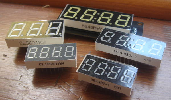
From the selection I ended up with there was an apparent pattern with the part numbers and for the samples obtained the corresponding values are shown in the table below.
It is not clear whether this is an industry standard or whether it is just a convention due to them mostly coming from the same white-label manufacturer but suspicion is it being the latter as there is inconsistency with the dots value.
Note that even though the 4041BS-1 has four decimal points only three of them can be used, as one of the pins is instead connected to the colon.
| Brand | Size | Digits | Dots | Polarity | Colour | Description |
CL |
Xlitx | |||||
36 |
Height in 100s of an inch. | |||||
40 |
||||||
56 |
||||||
3 |
Number of digits | |||||
4 |
||||||
1 |
Decimal points | |||||
2 |
Colon (time display) | |||||
3 |
Both dots & colon | |||||
A |
Common cathode | |||||
B |
Common anode | |||||
G |
Green | |||||
H |
“Ultra-bright” Red | |||||
S |
Red | |||||
W |
(Bluish) White | |||||
The pin-out is the same for all the LED displays including the three-digit CL5631BG for which pin 6 is not connected due to the absence of the fourth digit, and the pin functions are summarised in the table below.
When there is a colon it is wired to the pin for digit 2, and the pin for digit 1 is used for the second decimal point rather than the left-most first decimal point.
| Digit 1 | A |
F |
Digit 2 | Digit 3 | B |
| 12 | 11 | 10 | 9 | 8 | 7 |
| 1 | 2 | 3 | 4 | 5 | 6 |
E |
D |
Dots | C |
G |
Digit 4 |
Remarks
This article started out as a summary of the data-sheet for the TM1668 back in mid-June but as is often the case these days getting round to physically wiring up a circuit got put on the bank-burner until today, and a plan to take things further by building a reimplementation of my LED matrix tile was shelved as there are enough things competing for spare time as-is. I really disliked the butchered I2C protocol that theTM1637 uses whereas that used by the TM1620 and TM1668 are simple and clean.
My one regret is in hindsight the four articles done this year on this chip-set family ought to have been distilled down into two.