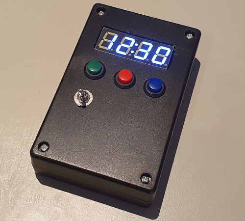
New timer enclosure
13 September 2025Even though it was made back in 2021 the LCD-based timer never got much use at the time but having recently bought it back into comission it has exhibited problems, and rather than retrofit it with a more suitable power supply decided to build a new one from scratch. This new one is based around Arduino making use of off-the-shelf components and firmware rather than diving deep into custom circuitry, and today the mini-project has finally been completed. To date it is the only significant electronics project since moving to Manchester last year.
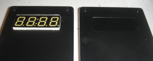
Mounting the display
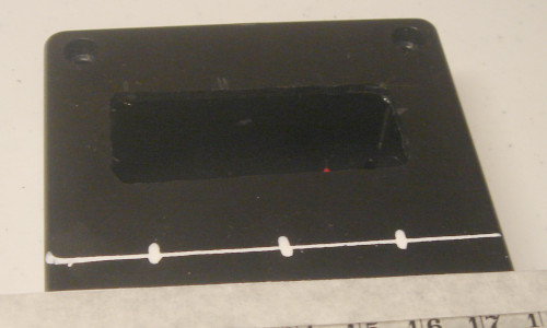
After initially using circular saw blades intended for wood the most effective tool for cutting the slot for the LED display was using a Dremel with a milling tip, a type of drill bit intended for cutting via side-ways movement rather than boring a hole. The edges were then finished off by filing them dowm so that the display would fit. Conveniently the blank space that needed cutting out matched the size of the LED display so relatively little clean-up was needed, unlike the better-detailed experimentation done using a more generic case.
The case also had mounting studs and two of them matched the display module's mounting holes, but the slot needed a bit of extra filing due to a slight misalignment between the studs and holes before the module could be secured in place using self-tapping screws. One problem is the height of the studs meant that the LED display module was not flush with the outside of the enclosure but this could be rectified via the use of washers, although this still left only two corners of the module secured.
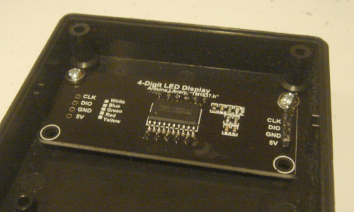
The eventual conclusion is that built-in studs were more trouble than they are worth, so they were milled away and instead the module would be secured by stand-offs that are glued into place. For this hot glue was used as it gave time to adjust the module before the standoffs became stuck, and while not as secure as superglue this was offset by hot glue being far less hazardous. Ideally a blank PCB would be used for stud placement but one was not available as the LED modules were bought as complete off-the-shelf components.
With saw blades friction tended to cause bits of plastic to fuse together and when drilling plastic tended to remain in long chafes, but milling instead creates a lot of small fragments which are a lot messier and more of a pain to clean up, especially with the way they get thrown about a lot. Suspected some of these small particles and dust from filing were responsible for irritation I noticed around the workbench having been away a few days that needed a through wipe-down to properly clean up, and I think one of them made it into an eye despite wearing protective goggles.
Mounting the buttons
The next stage is boring some holes into the enclosure into which the buttons will be mounted. Rather than drawing markings on masking tape I tried using a chalk pen which draws straight onto the plastic and can easily be wiped away afterwards, which is more convenient although the template lines need to be that bit thicker. A bit of masking tape on the ruler keeps the ruler clean though this is not really required.
After drilling pilot holes the one for the middle button was a bit off-centre, which was probably down to the marking being a bit off-centre and then placing of the drill bit also not being dead-on-centre. Unskilled hands bring errors which accumulate and the stop-start process of recording the procedure with pictures inevitably pulls away some measure of attention. Whatever the cause it is something to deal with so the required correction was measured and marked out.
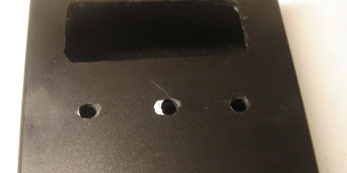
The actual correction was done by using the milling tip to extend the button hole to the left, and from here the original plan was to make use of progressively larger drill bits to obtain a holes of the correct size. However the buttons required a diameter larger than my largest drill bit and I suspect some of the mid-sized ones had also become blunted from mis-use over the years. A step cone drill bit would be more suited to the task but the best tool is a tape reamer due to its much better granularity, but from past experience using these is a lot of physical effort.
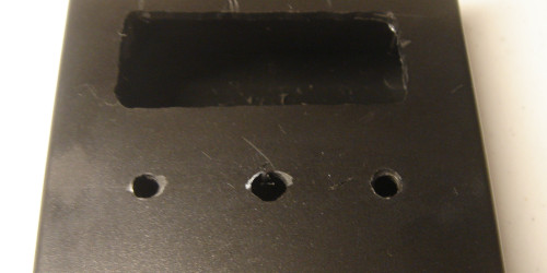
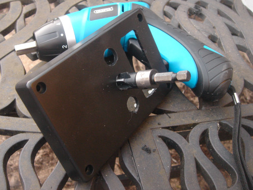
Fortunately I was able to obtain a tape reamer which was compatible with my electric screw-driver, as the much lower rotational speed it operates at compared to a drill makes it much easier to control. The buttons are far larger than ones I have used in the past going almost to the upper limit of the reamer, and had these needed to be done by hand they could have easily been 20–30 minutes each rather than that number of seconds.
Wiring things up
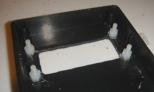
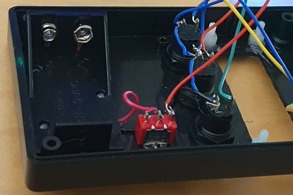
The power cell holder was hot-glued into place, the giveaway of which is some of the white glue poking through the mounting holes — for some reason there is no picture of this part itself after it had been put in place. The power switch and buttons had threaded sleeves which were secured in place with nuts, which was from the outide in the case of the power switch and from the inside for the buttons, the decision to put the power switch on the top rather than the side of the encosure being a last-moment change. Wire colourings were a bit akward since — for instance — red was used for both power and the red button.
Mounting the Arduino
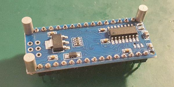
I have had bad luck with dud Arduino Nano clones in the past but one advantage of them is they tend to come in kit form rather than having pin headers pre-soldered. One option considered soldering wires directly to the board but in the end opted to put pin headers on the opposite side of the board and use du-pont connectors to attach the wires. For actual mounting several options were considered but the one ultimately used was making use of standoffs that would fit the M1.6 mounting holes.
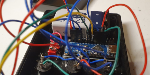
Due to uncomfortably close proximity to a capacitor only three of the four corners were secured, as the standoffs and bolts of the requird size only came in metal rather than nylon and hence might havw shorted out this component. The standoffs thsemselves were hot-glued into place but it took two or three attempts to get then right, due to the tight spacing making it difficult to position the glue pen. I had thought about using an alternative slow-setting glue but never got round to ordering samples in.

Overall things were a tight fit but in the end it all worked out. The sounder itself was mounted on a cut-down piece of perf-board but the clearance was sufficent for it to be bolted towards the top of the lower part of the enclosure, which can be seen at the top of the picture above.
Remarks
One of the crimped connectors broke during final assembly up in Manchester last week but with that repaired today this timer project has reached its goal. It was somewhat spontaneous especially considering the significant investment and part of me wants to do it all over again but have come to the conclusion the Manchester apartment is not suitable for the type of work. Realistically there is not the space other than for sub-set of electronics equipment to be shuttled up on a per-project basis, and in practice such project get left by the way-side.
The timer turned out to be eight seconds slow over half an hour but for its purpose this error is acceptable. It could be fixed by tuning the interrupt delays but this is a tedious process and prefer not to reopen the case just to do this, as some of the wiring is a little delecate. In terms of pass-time the project has served its purpose and there are other things on my to-do list.