LED matrix tile respin
10 July 2024Having decided to revive my LED display system based around the Multicomp
702-0194 LED matrix modules it was clear that I needed to build some extra matrix tiles that are the higher-level building blocks for a longer display.
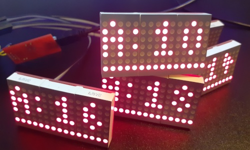
The idea with these is each tile handles the refresh of three matrix modules and the I2C interface is used purely for the distribution of updated display data, and then a display would consist of three or four of these tiles for a total of between 45 and 60 columns.
Due to the amount of time since the previous tiles were designed and built some changes were made and the firmware rewritten.
Circuit design changes
The PCB is almost identical to the previous iteration with the one major change being use of a QFN package for thePIC16F886 microcontroller rather than the previous SOIC packaging, which hand-in-hand comes with the addition of an on-board programming header.
I forget whether the change to QFN was down to the SOIC variant being unavailable at the time of the PCB respin or was a desire to use a smaller chip, but either way the previous programming via a flashing clip was tempremental arrangement that needed replacing.
Physical dimensions of the PCB as well as the location of the LED modules and I2C interface were intentionally unchanged so that both the older and newer tiles could be used interchangably.
Some decoupling capacitors were also added as it is good practice to include them, although at time of writing they were not populated.
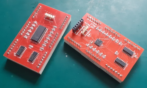
The PIC16F886 has enough pins to negate the need for the 74HC238 3-to-8 decoder chip but for whatever reasons the existing design used one and the desire here was to leave the functional schematic unchanged.
While this would allow the same firmware to be used on both old and new tiles the actual goal was to minimise the scope for errors.
This respin is about getting more units rather than correcting faults and maintaining commonality happened to be the most expedient approach to getting things done.
Reflow soldering the QFN
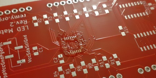
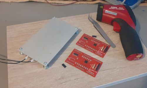
A disadvantage of QFN chips is they cannot easily be hand-soldered so instead they were hot-plate reflowed using a new experimental setup based around a cheap rework heater, which went quite well even without any form of automation. In summary the heated PCB pads are tinned using solder wire and the chip put in place, the one trick being how surprisingly little flux needs to be used with the amount shown in the picture below being about right. I am pretty sure pressing down on the chip with tweezers until the solder had solidified helped ensure good connections rather than allowing flux to lift up the chip, although this may be a sign that even the small amount of flux shown in the picture is too much.
Board testing
Unlike other chips the risk with QFN packages is disconnected pads rather than solder bridges so a test firmware that sets all pins to high was flashed and each output checked with a multi-meter — perhaps due to residue flux a better electrical connection was obtained via the resisitors rather than the through-holes. However this was perhaps a bit over the top as the chips that needed to be redone would not even connect to the programming tool, but I had the spare time and would not be able to do any rework once the LED chips were attached.
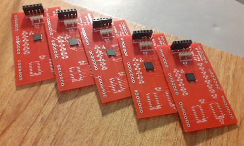
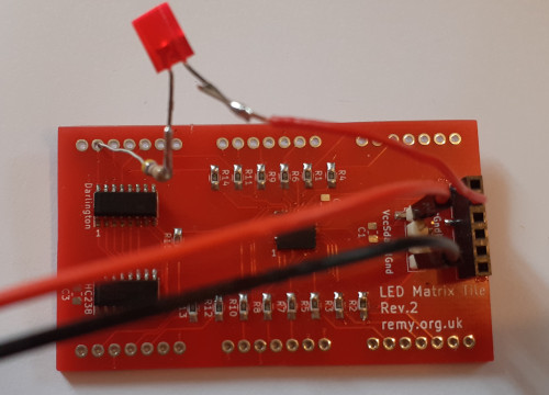
Due to circumstances the Darlington and logic decoder chips were added some considerable time after the main micro-controller was installed and with all surface-mount parts in place the only component left to add was the LED matrix chips themselves, but being the one component that was not expendable it made sense to test the board as much as possible before they were soldered into place. The smoke test used was to wedge in one of the LED chip as shown below — with only half the pins connected it was an imperfect test but it shows that all chips within the circuit were at least partially functioning, and in my experience chips are either fully functioning or are dead.
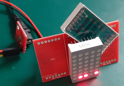
Of the five boards tested this way three passed and two failed. This was not too surprising since soldering on of the two chips did not go smoothly due to not having done any PCB work for some time beforehand, but it is still irritating given how much of the circuit was alreadty known to be working as intended. Further testing with one board complete with LED chips soldered in place showed that one of the row current sinks was non-functional, which was tracked down to an open-collector pin with a dodgy solder joint — a make-shift probe made from a resisitor was used to test the four other boards, and unfortunately only one of these was problem-free.
Board rework
With two boards failing the above smoke test the presumption, which turned out to be correct, was the logic decoders being the problem and these were removed using the same hot-plate that was used to reflow the micro-controllers. The rest of the circuit seemed operational given the limits of what could be tested so the sane thing to do was do rework and replace the suspect integrated circuit chips rather than abandon these two units. Since the hot-plate automatically tops out at 230°C and even then take 90 seconds to get there it is easier to manually switch the plate on and off to limit the temperature rise rather than use any form of power switching circuit.
Rework following the later “LED probe” test consisted of using hot-air to remelt the solder on the decoder and Darlington chips, and the components then pressed down as the solder solidified. Unlike the hot-plate this meant that one chip could be done at a time without the risk of other components becoming dislodged, and it was about time I got some experience with using the hot-air rework station. Of the three boards that were reworked using hot-air one was fixed; one required a little extra solder to fix a remaining dodgy connection on one of its output pins; and one was messed up with the Darlington chip being knocked out of place.
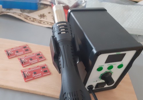
The displaced chip is almost certainly in full working order but it was just less hassle to replace it with a fresh one than to try and clean the solder bridges between the pins on the chip that came off.
Availability of parts
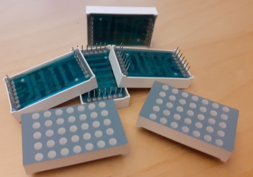
In the latter part of 2019 I pretty much cleared out Farnell's remaining stock of703-0194 red row-cathode chips, of which I easily located 35 units and have a fairly good idea of where a further 55 units are.
Realistically this is likely more than I will ever use but even at the time I knew it was a case of get them while they are cheap.
Just as well as while the Kingbright TA12-11SRWA appears to be a mechanically and electrically compatible substitute it costs about five times what I paid, and I suspect they might also be discontinued before long.
All other components were readily available if not within my existing stocks, although the unit cost of the PIC16F886 QFN chips has gone up 40% since I ordered them in October.
I had seen notifications that the SOIC variant of the PIC16F886 was no longer being stocked but Farnell has since done a U-turn and are stocking it again.
Nevertheless I find myself more often these days having to source things from Mouser as Farnell have stopped stocking a lot of other components over the last few years.
They are still my go-to vendor but I am not as impressed with them as I used to be.
Firmware
The previous matrix tile firmware was written in C but with large portions using inline assembly and the resulting inefficient mess is why shortly afterwards I stopped using C for Microchip PIC microcontrollers, and for this respin the whole firmware was rewritten in pure assembly. Over the last three years I have not written much firmware and I am starting to gravitate towards ARM and Arduino so it is fair to say I am a bit rusty writing things for Microchip microcontrollers, but it is still interesting if a little frustrating to get back into it. ThePIC16F88x instruction set has several differences compared to the PIC16F182x chipset family I almost always use these days when choosing a Microchip part, and while most of these differences are not an issue for this particular firmware they do reinforce my general migration towards non-PIC microcontrollers.
Like the three firmware-based circuits built last year the vast majority of the firmware development was done using GPSim and it was just the final addition of the I2C interface routines before actual hardware was used.
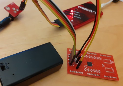
This approach is not without its gotchas. Easy visibility of all register values is balanced by the ease that incorrectly set bits are missed, which in turn an incorrect image is shown by the LEDs — the culprit as it turned out being a rogue carry bit from a previous operation. There was one other error related to use of indirect addressing but not sure if this was a mistake on my part or whether it was something GPsim accepts, as GPsim is known for not always being 100% accurate in its emulation.
Single indirect memory access
TheFSR and INDF registers effectively provide a way of implementing pointers which in turn are an essential ingredient for implementing arrays, an example of which within the matrix tile is the data buffer used by the I2C reception code.
Unfortunately there is only one such register pair on the PIC16F88x chipset family whereas two are needed in circumstances where data is read from one array and then written to another, which makes the conversion of the incoming column-based I2C data into row-based data for the refresh process a pain.
The choice was to do a partial conversion every refresh cycle and write directly to the output ports which causes issues with duty cycles, or hard-code the entire conversion without use of indirect memory access which is inelegant.
A snippet of the latter for a single line is shown below:
CLRF rowdata BTFSC coldata + 0,0 BSF rowdata + 0,0 BTFSC coldata + 1,0 BSF rowdata + 0,1 BTFSC coldata + 2,0 BSF rowdata + 0,2 BTFSC coldata + 3,0 BSF rowdata + 0,3 BTFSC coldata + 4,0 BSF rowdata + 0,4 BTFSC coldata + 5,0 BSF rowdata + 0,5 BTFSC coldata + 6,0 BSF rowdata + 0,6 BTFSC coldata + 7,0 BSF rowdata + 0,7 BTFSC coldata + 8,0 BSF rowdata + 1,0 BTFSC coldata + 9,0 BSF rowdata + 1,1 BTFSC coldata +10,0 BSF rowdata + 1,2 BTFSC coldata +11,0 BSF rowdata + 1,3 BTFSC coldata +12,0 BSF rowdata + 1,4 BTFSC coldata +13,0 BSF rowdata + 1,5 BTFSC coldata +14,0 BSF rowdata + 1,6
This results in a lot of cut-n-pasted code when done for all seven rows although ironically in terms of execution time it is a very efficient two instructions per LED dot, and due to the way conditional branches are handled this execution time is independent of the data. This latter approach was used in the final version of the firmware. Having only a single indirect register also means that it has to be shared between both the LED lighting and I2C routines, and since a refresh and I2C transation may overlap their respective code paths have to setup indirect memory access from scratch each time.
No linear memory model
The linear memory model has a separate memory address space starting at0x2000 where the general purpose registers of all the banks appear as a single contiguous block without any of the special-purpose or shared data registers mixed in, which is particularly useful in instances where a block of memory exceeds the 80 bytes that each bank typically indivudually has for data.
Although not an issue here since the matrix tile firmware does not need a huge amount of memory the PIC16F88x does not include this memory addressing mode, which seriously limits the usefulness of the chipset family for data processing.

No branch/return using working register
TheBRW instruction branches to a location defined by a software-calculated value and RETLW provides a way to return a value from a function using a single instruction.
These two instructions together provide a way to implement both jump tables and data lookup tables, the latter which was used for voltage-to-temperature lookups within the thermocouple control circuit created a few years ago.
Neither instruction is implemented by PIC16F88x which again is not an issue for the matrix tile firmware but is a headache for firmwares that need to implement a state machine.
I2C extended functionality
Although I am unsure whether the I2C handling code in the previous C-based code is entirely correct given how long ago it was written I ended up more or less doing a direct translation of this code into assembly rather than use the much more recent assembly-based code used for the I2C slave device. Aside from the names of the I2C registers for thePIC16F88x being slightly different such as SSPCON rather than SSP1CON1 and SSPCON2 instead of SSP1CON2, this chipset family does not have the address-hold & data-hold functionality the newer assembly-based code used and hence the latter's structure was unsuitable.
The code has yet to break in any way and until it does there is no real incentive to go diving deep into the relevant sections of the data-sheet.
Future plans & remarks
The ultimate goal is to create a self-contained LED display consisting of multiple tiles, and the next stage is to create power and control circuitry which hosts matrix data created using my Python-based editor. A control PCB had actually been fabricated back in 2019 that was intended to be programmed via RS232 but it was abandoned due to a design screw-up which resulted from its rushed design. Since then the idea has shifted to instead pull matrix data off a removable EEPROM chip, and such a circuit is currently a work-in-progress on prototyping board. An alternative would be to have a circuit based around a NXP-based USB board but that would be a huge increase in what is already a large umbrella project of an LED display system and infrastructure.
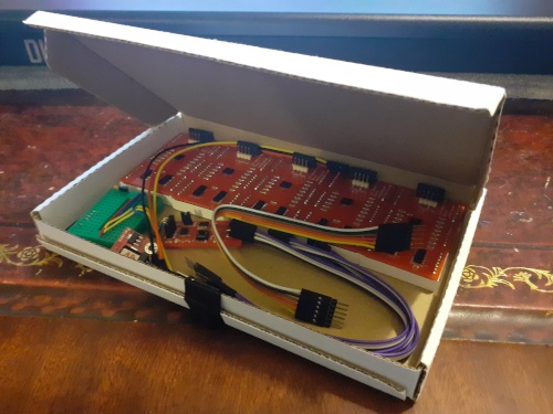
The whole LED display project was overtaken by events on multiple occasions and this extends to this matrix tile respin. Although the PCBs were ordered mid-August last year it would be the dying days of December before any soldering started, it was into June by the time the firmware was complete, and it is only this week that all five tiles are fully operational. This contrasts with 2018 when it was not unusual for such a project to last two or three weeks all-in so I do sometimes think of external circumstances then and now that cause this difference. Fortunately the overall project is one that could be cut up into self-contained chunks.