Hard-wired night light
25 June 2023This circuit is a basic timed night light that is intended to be powered from lithium-ion power cells, the purpose being to provide a little light in otherwise completely dark places. The project was started when such a situation resulted in an accident that was waiting to happen and off-the-shelf solutions were less than satisfactory. Although it would have been simpler to make a microcontroller-based solution — which is currently being done as a follow-up project — the approach here is a hard-wired one based around counters and decoders because that is the type of electronics I prefer as a passtime, and the process of making it is as important as the outcode. Operationally each of the switches indicates which intervals over the LED(s) are lit for.
Circuit design
A Texas InstrumentsTPL5110DDCT low-power timer is used as a clock source and it is setup to use the maximum two-hour interval that is supports.
It normally expects to be attached to a microcontroller which in turn provides a reset signal that deasserts the clock signal but in this case a resistor-capacitor pair (R1 and C1 — nominal 1kΩ & 10μF respectively) is used to provide this done signal six milliseconds after the output is asserted.
This is turn feeds a SN74HC161D counter which provides binary values between zero and eleven, with some logic implemented using N-type MOSFETs that causes a reset when the value of twelve is reached.
This four-bit binary value is then expanded by a 74HC4514D into individual lines (B0 thru B11) which go into the next stage.
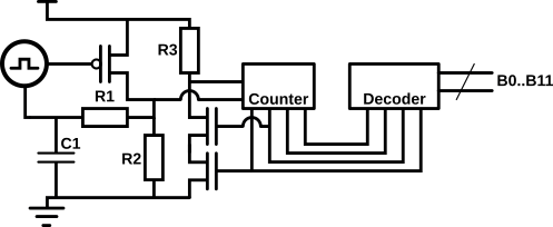
An alternative design would be to have a barrel shift register where the high bit is circulated between the output lines but that has the complication of how the initial high bit is set of circuit start-up.
Not shown in the circuit is manual reset buttons used to force a known circuit state although in practice the counter is zeroed on start-up and an initial pulse from the timer shifts the “current” time onto the second two-hour time block.
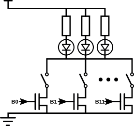
Each line B0 thru B11 from the previous timing and counting stage is effectively AND-ed with its coresponding switch, and if any of these AND outputs are true the lower power rail of the LED array is grounded which in turn powers the LEDs.
The switch and N-type MOSFET pairs are basically NAND gates and one insight was realising that the switches could be used directly rather than in turn controlling their own MOSFET.
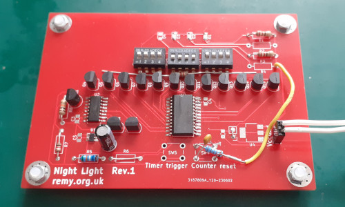
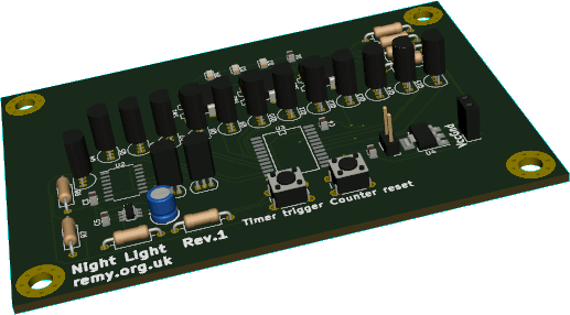
PCB design & fabrication
Even though KiCAD version 7 was released a few months ago I have stuck with using KiCAD 5 since so far there seems to be no real advantage in upgrading. One way or another all the component symbols and footprints required for this project were available, such as using the footprint for the74LS161 in place of the pin-compatible 74HC161, and the overheads of getting upto speed with changes in the newer versions so far have not been worth it.
My current preference is for projects that use my existing stock of through-hole components so the majority of the PCB designs I have had fabricated this year have been break-out boards for surface-mount components.
For fabrication this was part of a four-design order via JLCPCB which with Civod-19 era delays in shipping now gone is back my favoured foundary, and being part of a relatively large order decided to pay the extra $10 for faster FedEx shipping that resulted in a week turn-around time rather than the usual 2-3 weeks.
This is not as fast as the European-based Aisler which I used a lot back in 2021 & 2021 but last time I checked they are competative if things like RoHS compliance are a concern.
For personal projects I am fine with lead-based products but anything that would reasonably leave my possession would need to be lead-free.
For this project there seemed little value in trying to assemble a parts list since a good portion of the PCB footprints were left unoccupied, and many of the components actually used were generic passive ones that were sourced around five years ago so may well no longer be available under the order codes they are stored under.
Quite often components are drawn ad-hoc from stock that is a mix from multiple vendors and manufacturers so in many cases no track is kept of where things were originally from, and even attempting to do so is not worth the effort.
The Texas Instruments TPL5110DDCT timing chip, SN74HC161D counter, and 74HC4514D decoder chip are the important components in this circuit — and of these the decoder is no longer manufactured and the counter looks like it may well be discontinued in the near-future as well.
Counter reset logic faults
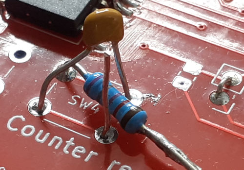
Initially none of the counter output bits were going high but this was soon traced to the active-low reset pin not having a pull-up resistor, and this was fixed by bodge-wiring in a 78.8kΩ since the unpopulated counter reset switch and one of the LED protective resistors provided easy connection points. The sub-circuit that asserts the counter reset was supposed to trigger when the output from the counter reaches1100 but in the transition from 0111 to 1000 the high bit turned on its MOSFET before the other MOSFET controlled by the second-highest bit had fully turned off.
Observing the momentary signal on the reset pin was close to the limit of the oscilloscope but its presence confirmed the problem was an early reset rather than a faulty counter, and putting a 9nF by-pass capacitor between the reset and ground pins was sufficent to absorb the glitch.
Because the low-power timer initially asserts its output there is a counter increment on initial powerup that causes the second transistor to become the active one, so the lefthand-most switch actually corresponds to the last 2-hour period in the 24-hour cycle.