Lithium-ion power pack
05 April 2023In part inspired by various videos by Big Clive one thing I had been collecting is the lithium-ion power cells that are frequently discarded because the e-cigarettes they are within have ran out of chemicals to dispense, which to me seems like a huge waste. Having now got around half a dozen it was time to try putting them to use since they would take up less space and last longer than the 9-volt square power cells I have traditionally used. The end result is a USB-charged device that outputs a smoothed 5 volts.
Power management
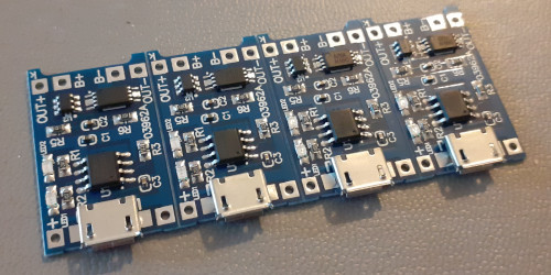
Lithium-ion technology requires much more power management than other storage methods, as they are particularly sensitive to being mistreated by over-charging, over-discharging, and in the case of multiple cells unbalanced voltages. They store a lot of energy for their size so shorting them out is dangerous, and if they catch fire they are exceptionally difficult extinguish. Rather than even attemting to design my own, which most likley would pretty much involve a data-sheet reference circuit, it seemed wiser to use off-the-shelf power management modules based around theTP4056 controller chip.
Charging is via USB although there is an option for a different power source.
The power cells I have scavanged are all nominally rated at 3.7 volts but far as I can tell from reading around they have a maximum of 5.4 volts — and hence more correctly should be labelled 3.7v/5.4v — and the latter is what should be used to charge them.
The 3.7 volt rating is what they have when between about 20% and 80% charged and the voltage drops off rapidly when they are down to 10% charge; cells below 3 volts are considered dead and start to have permanent damage if allowed to discharge further.
There are other lithium-ion voltages out there but they are few and far between.
Voltage boosting
One slight problem with lithium-ion power cells is them having an output of around 3.7 voltss, but the electronic circuits I build typically need a 5-volt supply so some voltage boosting is required. My power requirements are typically way below 100mA and boosting three and a half volts to five volts does not strike me as a big jump. As with the management module my plan was to just buy some off-the-shelf booster circuits but I had trouble finding ones that matched my requirements, so I ended up creating my own based around the Analog DevicesLTC3525ISC6-5.
It was sent for fabrication mid-Febuary and was intentionally made to have at least one dimension common with the power management module that supplies it.
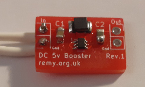
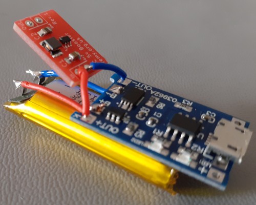
Hand-soldering the LTC3525ISC6-5 chip was tricky due to its small size, possibly being the smallest component I have ever used with the 0805 capacitors next to it showing the scale, and what did not help was the printing on the chip becoming unreadable even under a microscope when it was doused in flux.
This caused problems as the chip's orientation was indicated by a small triangle rather than the usual notch or dot.
Plenty of rework effort was needed but in the end all three of the boards soldered up were made to work.
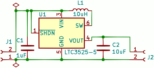
Booster circuit design
The voltage booster circuit is an almost direct implementation of a reference design from the data-sheet and I suspect that one or both of the capacitors could be omitted, but it is already such a simple design that there is no point doing anything other than retaining them. In hindsight I probably should have put in extra pads for extra decoupling capacitors but experimentation is not the purpose of this project. The Gerber files used for fabrication are available from by Bitbucket repository.
List of components
The two capacitors are ones from stock bought about five years ago and they are of the 0805 package I have standardised on since these are the smallest I can easily hand-solder without using any optical aids. These were from my normal go-to vendor for components which is Farnell but the range of in-stock items is not quite as good as it was a few years ago and I have lost track of how much back-ordered stuff I have with them. The booster chip and inductor I bought in specially from Mouser over in the states since both had free shipping.
| Pad | Component | Manufacturer | Part number |
U1 |
Voltage booster | Analog Devices | LTC3525ISC6-5 |
L1 |
10μH inductor | muRata Electronics | LQH32CN100K53L |
C1 |
1μF 0805 capacitor | Wurth Elektronik | 885012207022 |
C2 |
10μF 0805 capacitor | Multicomp | MCTT21X106M6R3CT |
Packaging
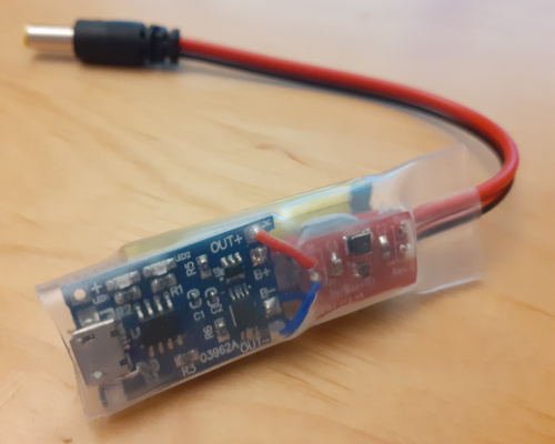
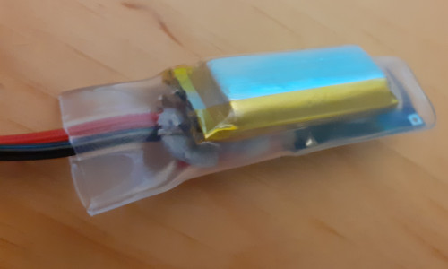
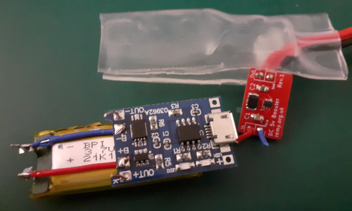
I took the same approach as Big Clive and encased the circuit boards with transparent heat-shrink, but it is rather hit-and-miss trying to source the right size from E-Bay so ended up buying stock in from three or four different sellers. For all its faults E-Bay is the best bet for stuff like this if you only need small quantities but at times it is hard to work out what is actually on offer. After much thought I decided to stack the power cell below the management board and place the voltage booster board downstream within the shrick-wrap tubing, the reason being this meant the power cell wires would come in from below whereas the connection to the voltage booster are soldered in from above.
A barrel jack cable was then added to the booster output and the whole assembly then encased in shrink-wrap. I was a bit worried about having to expose the lithium-ion cell to hot air but reassuringly it did not take long for the shrink-wrap to do its job. Some blu-tack was used to anchor the booster circuit so that internal contacts are kept apart.
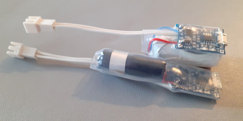
Stand-alone cells
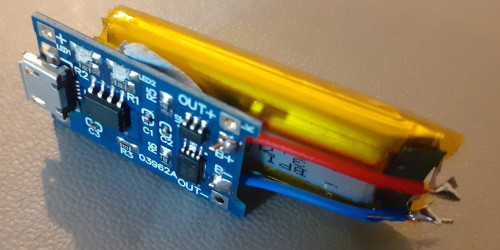
Due to delays getting the barrel plugs required for the all in power pack that was the original goal, some stand-alone (i.e. no voltage booster) power pack assemblies were made that used mini-molex leads. These would most obviously be useful with 3.3-volt circuits but I very rarely use 3.3-volt rated components and even then most of those were USB bus powered. However omitting the voltage booster made them a lot easier to construct, not least there being fewer connections that could become shorted and the difficulty of soldering up the booster circuit itself, and this is how future units will likley be made.
I am unsure what leakage is caused by either the power management or voltage boosting circuits but they for certain are both non-zero, and I would not be surprised if having the voltage booster permanently in place makes the leakage significantly worse. However in the case of the all-in power pack it was still giving a steady 5-volt output with a 460Ω load a few weeks after it was wired up with the booster circuit.
Remarks
This was one of those projects that could have been done in an afternoon but waiting for the right components and materials stretched it out to almost two months, and getting anything other than ancedotal performance data would have stretched it out even further. Time will tell if these power packs prove to be an adequate replacement for my current PP3 cell holders.
(Added June 2023): The voltage boosting imposes a current-draw at all times but it appears that when the power-control board cuts off power output due to low lithium-ion cell voltage, this is a latched cut-out that does not reset if there is any load on the output. Result is a bricked power supply so as shown in the picture above the power cell has since been separated from the booster circuit.