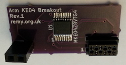
Kinetis KE04 breakout
02 March 2020This is a simple breakout board for the Kinetis KE04 chip, which is one of the few ARM Cortex microcontrollers I have come across that can be run using a 5-volt power supply. While the PIC chip architecture has its attractions, the ARM architecture and development eco-system is vastly superior for firmware development that is more than just bashing bits around to GPIO pins, and I will most likley favour it for future prototype circuits.
Circuit design
The circuit design as a whole is nothing special — the main part is a fan-out of pins to a board-to-board connector, with most of the rest going to an interface for firmware flashing. The circuit has a simple overall purpose, and that is the use of an ARM microcontroller with prototyping board. As a result the interesting detail is with the individual parts, which are covered in the next few subsections.Programming interface
This breakout board is intended to be programmed via my MicroMatch adapter and one motive for making this breakout board is to end-to-end verify that my custom flashing interface works before I use it on a larger circuit. It is a physical interface I chose trying to minimise both PCB space and component cost, the latter in response to the price of mini-ITC connectors — had this breakout board used a mini-ITC, it would have been the majority of the total cost of the circuit.Circuit interface
For the board-to-board interface I decided to opt for a single row of pins. Having two rows works well when using solderless breadboard, but there are issues with getting the alignment of the pins right, and two rows tends to be a pain with strip-board and perf-board. This is important as in practice I use soldered prototyping boards most of the time. The schematic showing the interface is below.
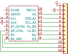
I decided that pins required for programming should be dedicated to this task, which leaves 11 pins for the main interface. Pin 5 was left out so that the number of connections on the external connection would be even rather than odd. The two power pins are both at one end so that it is possible to use a connector that has less than 12 connections.
Power interface
As well as the power connection on the main interface, there is an auxilliary power socket that allows the board to be powered when not plugged into a host circuit. This is intended for use when the microcontroller is being reprogrammed. To save space it is assumed that any external power supply is already regulated, and for this purpose I have a mini-PCB that carries a power regulator.Board production
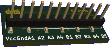
One thing I considered important was to have the main interface running down the middle of the board rather than an edge, so in order to keep the board balanced I opted to use a surface-mount pin header rather than a through-hole one. This can be seen in the rendered image of the under-side below. In hindsight the board could have been a lot narrower had I used entirely surface-mount components, but I felt that this was not worth the effort.
Fabrication
For this board I used OSH Park and once again was upgraded for free to the express service — such upgrades seem to happen about half the time, and might be due to the circuits I send to them being relatively small. From memory delivery in the past has been slow, but this time round it was five working days, and the delivery record actually included all the hops outside of the US. As a result of all this end-to-end order turnaround time was only around half of what I expected it to take.I was going to try out a new fabrication service that had an introductory special offer on, but since it is based in China I gave it a miss due to the COVID-19 lock-down. Trying it out would more or less be a comparison against Seeedstudio and even then the only scope for a major difference is with delivery rather than the fabrication service itself — in practice I suspect that any saving in delivery cost will be at a huge increase in delivery times, in which case I would prefer to pay the few extra dollars.
Panelisation tacks
One thing I have noticed with PCBs from OSH Park is that the remains of panel support tacks — the thin strips sticking out of the edges in the picture below — are left in place and need cutting away. From what I can ascertain OSH Park put multiple designs onto the same panel separated by milled slots, and when they get the panel back from what may or may not be an outsourced fabrication facility, they then simply snap the thin support tacks that hold the individual customer PCBs together.
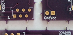
To be fair for little more than $1 each including shipping this is not something I am going to complain about.
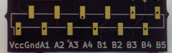
Labelling errors
As can be seen by comparing the PCB with the interface schematic the labelling is messed up —A4 should be B0 and misalignment means B6 is missing. Not a critical error but silk-screen mistakes have been quite common on some of my recent circuits, and in this case it can be put down to rushing out the fabrication order.
As a general rule as long as the schematic is correct then the odds are that the circuit will not have any critical issues, so the schematic is where I focus my attention when doing pre-fabrication checks — KiCad does a lot of automated checks so things like crossed tracks that stung me in the past get flagged up automatically, but as this case shows it still allows some mistakes to slip through.
Components
Below is a bill-of-materials for the circuit board, together with part numbers and vendor codes, which I now include as standard in all electronics articles. In this case everything was sourced from Farnell, although at time of writing they are out of stock of the Kinetis KE04 microcontroller. I have omitted price information as most of the components are surplus stock I bought for previous projects.
| Description | Manufacturer | Part number | Vendor | Order code |
| Kinetis KE04 TSSOP-16 | NXP | MKE04Z8VTG4 |
Farnell | 2409294 |
| MicroMatch connector | TE Connectivity | 2178710-6 |
2473349 | |
| 12-way pin header | Multicomp | 2211SM-12G-B1-TB |
2847176 | |
| 2-way receptacle | Multicomp | 2212S-02SG-85 |
1593458 |