MicroMatch ARM connectors
11 December 2019While I recently managed to source a receptacle for the 1.27mm (0.01 inch) pitch mini-IDC connector that is used by the standard JTAG/SWD 10-pin cable, and this was used on my ARM-based I2C adapter, the part is vastly over-priced for what it is. The Samtec
SHF-105-01-L-D-TH weighs in at €2.48 each, which is basically €3 once sales taxes are factored in — whatever the reason as far as I am concerned this is too much, so I looked at alternatives. The resulting custom-made adapter is shown below.
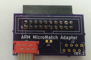
As an alternative I opted for the MicroMatch range of connectors from AMP/TE Connectivity where even individually the receptacles can be sourced for around 30¢ each. Although not quite as small as the mini-IDC connector I get the impression that they are more robust, and the staggered mounting pins makes them easier to solder.
Design
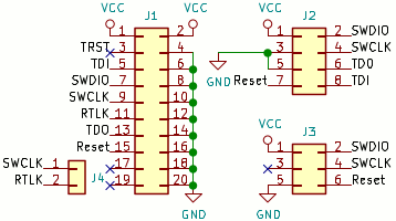
Although made from scratch this adapter was heavily influenced by my previous programming adapter — this includes using a receptacle footprint for which I actually used a plug component soldered onto the under-side of the board, because I knew that combination worked and I actually liked having the component orientated that way. Otherwise this circuit is little more than a basic breakout board, and the schematic is show below.
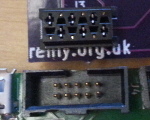
8-pin connector
I had originally intended to use a 10-pin connector and use indentical pin-outs as the standard 10-pin IDC wiring, but with three redundant pins I decided to opt for a slightly smaller 8-pin connector — being a custom connector there was no strict need to follow the standard, even if I used it as a template. The resultant pinning is shown in the table below — I decided not to includeTRST as none of the chips I have used to far make use of it.
| JTAG/SWD name | Connector | JTAG/SWD name | |
| Vcc sense | 1 | 2 | TMS/SWDIO |
| Ground | 3 | 4 | TCLK/SWCLK |
| Ground | 5 | 6 | TDOSWO |
| Reset | 7 | 8 | TDI |
6-pin variant
In practice I have almost always used SWD (Serial Wire Debugging) rather than full-JTAG, either because the chip only has those pins or because OpenOCD only supported SWD for a given chip, so I also decided to take advantage of the lower number of required connections in order to use the slighty smaller 6-pin connector. The pinning for this interface is shown below.
| SWD name | Connector | SWD name | |
| Vcc sense | 1 | 2 | SWDIO |
| Ground | 3 | 4 | SWCLK |
| Ground | 5 | 6 | Reset |
RTCK-TCLK shorting
The schematic for the OlimexARM-JTAG-20-10 which I used as a reference included the tying together of the TCLK/SWDIO and RTCK connections, so I included this as a jumper option on my previous programming adapter, and carried it forward to this adapter. For space reasons I gave it a 0805 footprint rather than a 2.54mm pin header in order to save space, and I am not entirely convinced it is actually nececcary since so far I have not seen any need to connect the two together.
Part numbers
The PCB receptacles have the manufacturer code of217871m-p where m is 0 for through-hole and 1 for surface-mounted variants, and p indicates the number of pins. The four that are relevent for use with this programming adapter are summerised in the table below.
| Description | Part number | Order code |
| 6 pin (through hole) | 2178710-6 |
2473349 |
| 6 pin (surface mount) | 2178711-6 |
2473358 |
| 8 pin (through hole) | 2178710-8 |
2473350 |
| 8 pin (surface mount) | 2178711-8 |
2473359 |
I had thought about getting the ribbon cables that can be soldered directly onto a PCB but ultimately opted for removable cables — the ones I ordered are summerised in the table below, although for some reason Farnell no longer stocks some of the shorter ones. My feeling is that anything much longer than 2 inches may help exceed maximum wire length tolerances, so I would not recommend the longer ones.
| Description | Part number | Order code |
| 6 pin 7.5cm | 2205061-1 |
2517936 |
| 6 pin 7.5cm | 2205104-1 |
2517996 |
| 8 pin 7.5cm | 2205105-1 |
2517999 |
Footprints
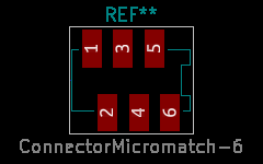
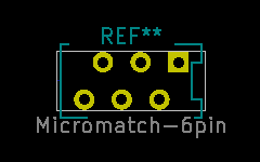
KiCad 5 includes a script for building footprints for surface-mounted MicroMatch connectors, and I used a generated footprints as templates for the through-hole connectors I used. The one tricky part is that the pads for the surface-mounted and through-hole variants are staggered on opposite directions, so I ended up mirroring and renumbering the pads. For comparison the generated and adapted footprints for 6 pins are shown below.
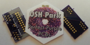
Fabrication
I had not used OSH Park for some time, the last major — and by major I mean one I wrote a correspondoing article — order being when I decided to try all three services I was familiar with at the same time for my 17-segment LED module, so for this PCB felt I should give them a try. The $5 per square inch (about 6.45 cm2) they offer for three PCBs with free shipping is actually quite good for my needs, so in hindsight I am surprised that there are not that many circuits I remember ordering from them. The standard service OSH Park offers seems to be a weekly batch to the foundry, but a significant portion of the time I i remember using them my order got upgraded to the express service due to spare PCB space on the panel — this order was one of them so my order which was placed on a Tuesday was shipped on the Friday the same week.
OSH Park now offer a solder paste stencil service which for me has been a show-stopper once or twice in the past, but the major issue I had with them in the past was delivery times. This PCB was shipped on a Friday and landed in my mailbox the Wednesday just under two weeks later, so order-to-arrival was a day over two weeks, but without the upgrade to the expediated service the turn-around time is potentially a whole month. With that lead-time I have normally opted to batch order stuff from Seeedstudio, but that is a discussion for a future article.
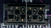
Polarisation issues
For some reason the receptacles are not polarised like the larger surface-mount ones I have experimented with in the past, since they have notches o both ends as shown below, which from my perspective is an irritating flaw. A programming connection is something that must not be connected the wrong way round, and one reason I chose these connectors was because they were polarised. At the moment I do not know whether the lack of polarisation is a property of the through-hole variants, or whether the smaller surface-mount receptacles also lack polarisation.
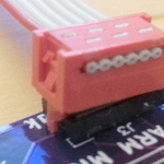
Another problem is the polarisation leg on the ribbon cable being too long, resulting in inability to fully insert the plug. This was solved by snipping off the lower part of the leg, but this is something I would prefer not to have to do — while part of the polarisation leg remains so that it cannot be inserted the wrong way round to receptacles that are polarised, as far as I am concerned notionally compatible off-the-shelf components should simply just work.
Remarks
Aside from the polarisation issues which were a bit of a disappointment, I feel the Micromatch connectors are a good choice for my needs. The 6-pin connector is actually a touch smaller than the mini-IDC connector it is intended to replace, but the PCB legs have that little extra space to make soldering a bit easier, and on the whole it feels that bit more robust. This adapter is a significant step on my migration from PIC to ARM, and I have other PCBs in the pipe-line that make use of the connector.
I have found that off-the-shelf solutions never quite satisfy all my needs, most notably needing an external power supply when I first started PIC programming, and this adapter PCB is the latest in a line of rolled-my-own infrastructure. Although it imposes overheads before I can actually get stuff done, I have found that in the longer-term it is the best way to do electronics, as it all adds to overall experience.