Home-made USB power bank
31 December 2025Back in September some of the lithium-ion cells harvested over past years were tested and a portion of them were packaged up as power packs, and of these one was converted into a complete DIY USB power bank. This bank is far too crude for me to even consider using it for charging electonic devices but that was not its intended purpose, rather it was made purely as a generic five-volt power supply intended for powering non-eletronic devices that happen to use USB connectors. This was also an opportunity for some enclosure modding and while this did not go as smooithly as hoped the result was still functional.
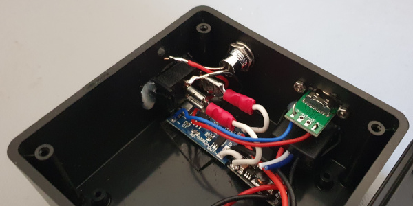
Power cells and connections
Most of the cells were harvested back in 2023 and had built up a sufficent stock that by the time the British ban on disposable vapes had come in enough cells had been scavenged to last for the forseeable future, and it was a mini-project a few months ago to get round to processing some of them. Two of the cells were disposed of as completely dead but in total seven were in good enough condition to make for power packs, with one powwer pack being a quad-cell.
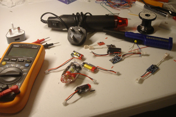
Unlike previous power packs made from harvested lithium-ion cells a connector was placed between the cells and the power management board rather than giving each cell pack its own permanent controller, as the latter only worked in cases where the power pack was to be kept stand-alone rather than charged in-situ without removal from what it powered. However quality of the pre-made connector leads left much to be desired and compared to the Molex connectors.
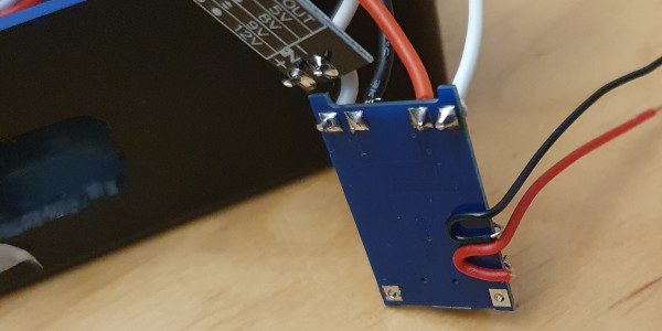
Power switch
The 6μA quiescent current of theTP4056 on the power management board is low enough that it can be kept permanently connected to a power cell but the same is not true of a voltage booster, with past attempts at this having to be dismantled due to the cell becoming bricked due to how discharge protection operated.
Hence the inclusion of a rocker switch so it can be switched off when not in use.
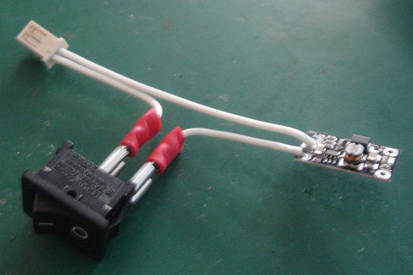
I am pretty sure these switches are intended to be used with spade terminals rather than wires being soldered directly as in the past trying to solder them has been a pain. Either way spades were used as they also make things easier to install by allowing disconnection/reconnection.
Voltage booster
The voltage booster is an off-the-shelf one that can output one of four fixed voltages, which was used since I had neither the desire nor the logistical ability to make more units of my own design, and would not surprise me if it is better performing or efficient. They were originally bought for a previous project that needed a 5-volt power supply but this project was eventually abandoned. The pre-wired USB socket was also an off-the-shelf component though I have doubts about the quality of the leads.
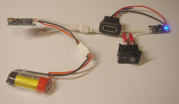
Since most of the components could be disconnected from each other it was possible to test the electrics prior to installation in an enclosure, but ultimatly for purposes of space the final wiring dispensed with most of the connectors with shorter wires being soldered directly.
Charging connector
I have a preference for USB micro and mini connectors since the receptacles are usually a lot cheaper than USB C parts as well as having more cables of these types lying around, so the original intention was to use a panel-mounted USB micro connector for charging. This involved careful soldering since the socket was probably intended for use with a connector rather than direct attachment of wires, and then shrink-wrapped the wires since it would not take much fore to detach the wires. In hindsight should have also used some glue or resin.
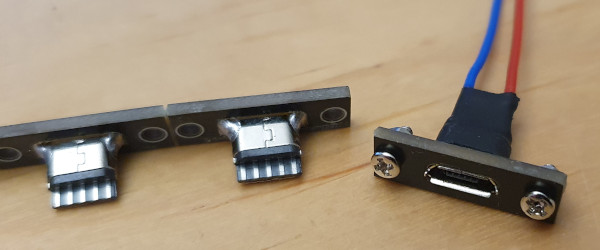
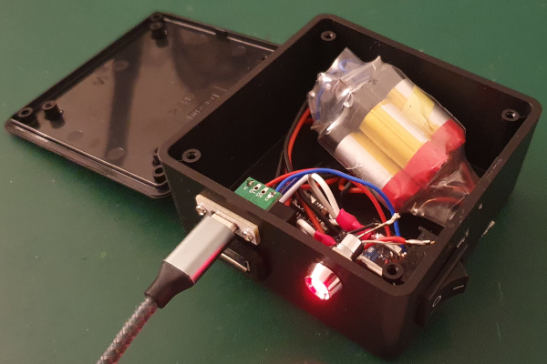
As it turned out one wire did become detached so just gave up and used a USB C socket that I had picked up from somewhere, as it had proper through-holes for direct soldering of wires. This needed the slot in the enclosure to be made wider which could have gone better, but at least the resulting socket was much more secure.
Charging light
As a last minute addition an external charging light was added, but this was difficult as it involved removing the existing charging LED and then hand-soldering bodge wires to the vacated surface-mount PCB pads. This was done by snipping them off with side-cutters and then cleaning up the pads with a soldering iron but in hingsight should have used hot-air instead. Was worried about the wires easily becoming detached so wrapper them around the power management board for extra security, and these in turn were attached to a panel-mounted LED that I happened to find while looking through some old component stock.
I had thought of instead cutting a slit so that the on-board LEDS can be viewed from outside the enclosure but I felt this was a cop-out and it would look ugly. Maybe if I had thought ahead I would have used a dual-colour LED rather than just wiring up one or charging.
The enclosure
For this project the interest is really in the craft side of creating an enclosure, with the electronics part almost being a means to an end. However due to past [issues with irritations][irritation] this is something that has to be done outside and as a result opportunities extremely limited. I do have drill bits for the Dremel but for basic holes it is just so much easier to use the seperate Draper drill, especially for lerger holes where the best results are from using a tape reamer. The one extra tool is a small file for finishing off the corners where the dremel leves a rounded edge.
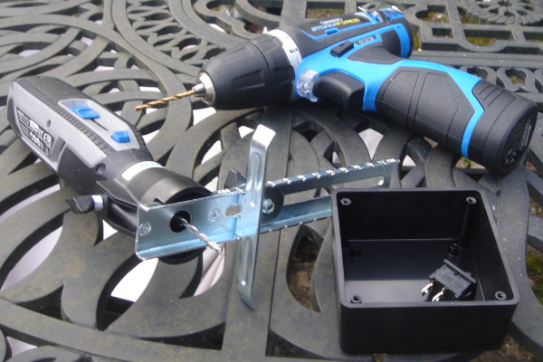
One difficulty in the past was trying to mill a straight edge and this project is the first opportunity to try out something to help with this: The 678-01 cutting guide which allows a cut to be parallel with an external edge and the image below tries to capture this operation.
In practice it is a bit tricky to use and the results are not perfect but it certainly makes a big difference compared to trying to do everything by hand.
This is one of those accessories I wish I had found earlier.
It is too easy to cut away more material than intended so the switch and power out port needed to be secured using hot glue. Originally the plan was to use a circuit which used detachable connections in order to avoid the need to do any soldering when it came to assembly but this was dropped as it would involve trying to cram in length of wiring far in excess of what was needed. The spade connectors were kept for the switch as these are difficult to solder, and the power cell comnnector was retained to allow cells to be swapped out, but everything else was simply soldered directly.