LED matrix control firmware
14 August 2023Ever since creating the LED Matrix Tiles back in late-2018 the plan was to create a controller that would drive multiple such tiles in parallel in order to create a single display, but this is one of many projects that had been put on hold by Covid-19 lockdowns and after almost exactly four years progress has been made. As one of a multi-part series this article covers the development of decoding firmware intended for a future master controller board based around a
PIC16F182x series microcontroller, and this firmware will be adapted once physical controller hardware becomes available.
The firmware and simulation enviornment are available from Bitbucket.
Display sequence encoding
Display sequences are stored in binary form as a series of single-byte instructions the encoding of which is shown below; these are created using wxLED which was developed back in 2019 and the rationale behind how sequences are structured is to make the common case of simple text expedient whilst allowing for some graphics through the use of custom glyphs. For decoding simplicity each instruction byte is self-contained with both the operation code and a single parameter, and the instruction encoding is summarised in the table below. For shift-up and shift-down multiple instructions are used to fill out a new row which is then displayed upon the Done instruction, whereas data instructions correspond to an individual column which are (usually) displayed immediately — silent column loading shifts columns into the buffer without any delay for later display all at one which permits content appearing immediately rather then scrolling in.
| Opcode | Encoding | Description |
Data |
0ddddddd |
Shift column from right |
ShDn |
100ddddd |
Shift rows down from above |
ShUp |
101ddddd |
Shift rows up from bottom |
Wait |
110ttttt |
Time delay |
- |
1110xxxx |
Unused |
- |
111101xx |
|
- |
111110xx |
|
- |
11111100 |
|
Load |
11111101 |
Start silent column loading |
Done |
11111110 |
Loading finished |
Halt |
11111111 |
Stop display |
There is a fixed delay after each line or row is shifted in with longer delays being specified by an explicit wait instructions. The shift-up and shift-down instructions have five parameter bits since this is how many columns each LED matrix chip has and hence will be an exact divisor of total display width. There is space for additional instructions and one likely candidate is a repeat instruction that would allow for a form of run-length encoding, but how this unused space is split up is something to be decided if and when the need arises.
Simulation setup
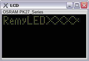
The main purpose of this sub-project was to develop firmware-based functions for the decoding of sequence instruction streams, so a gpsim circuit was setup which made use of the built-in graphical LCD display which is based on theSSD0323 controller chip, with sequence instructions loaded from file into the microcontroller's EEPROM.
The original intention was to use a PIC16F1828 or PIC16F1829 but since gpsim does not support these a PIC16F1823 coupled with an I/O expander is used instead, but ultimately the use of an LCD display was to easily check that the contents of the output buffer is correct.
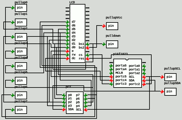
A simulation schematic is shown below although it is difficult to follow the connections.
When physical controller hardware becomes available the LCD display routines will be replaced with code that dispatches the column data off to an array of LED matrix tiles via I2C, and most likely the sequence instruction data will be loaded off an external socketed EEPROM rather than that built into the microcontroller.
Originally the plan was to use the presumably simpler 100x32 display based on the SED1530 but was unable to locate a useful data-sheet for the chip so ended up using the SSD0323 based one instead.
As is typical the data-sheet is a bit confusing at first and I suspect that gpsim only implements a subset of the listed commands but on the whole figuring it out had fewer issues than the text-orientated LCD displays based around the HD44780 chip.
Just stuffing in pixel data in an infinate loop worked, the only real complication being the realisation that it is four-bit grey-scale with two pixels per byte.