Manual EEPROM reader/writer
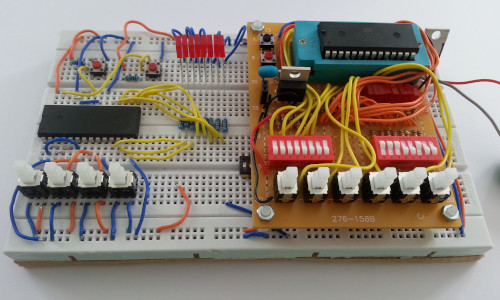
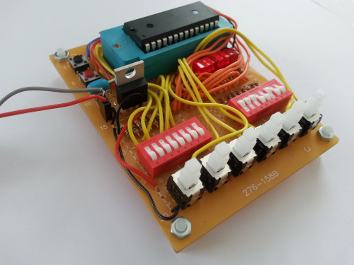
10 October 2021This is a remake of the previous experimental EEPROM circuit that is instead mounted on soldered prototyping board, since I wanted to keep the circuit but also needed to reclaim the prevoiously-used solderless breadboard for other projects. In the process I wired up all the address bits to switches rather than just the lowest few, and made changes to how the data pins were connected so that it is not possible to accidentally burn out the EEPROM with a short-circuit.
Circuit design
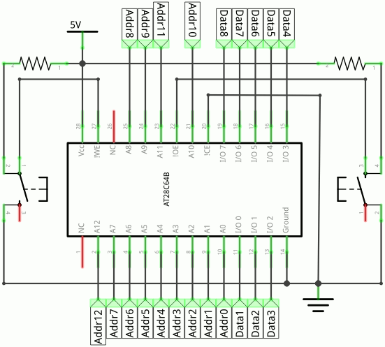
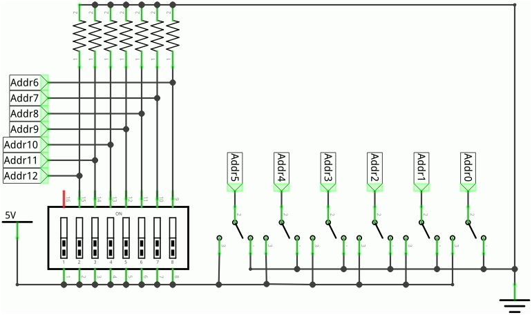
The circuit boils down to an EEPROM chip wired up to mechanical input switches, and does not even make use of de-bouncing circuitry since any bounces simply result in the reading or writing of the same memory address. The only gotcha with building the circuit was the location of the top five address pins — the bottom eight are all next to each other in order but the higher ones are a bit scattered, and it would not surprise me if I have actually miswired one or two of the top address bits.
Data switches
The experimental circuit used a MulticompMCTIIR-08-T 8-channel SPDT DIP switch that also included an open setting but it was a pain to use since it needed a small screwdriver to change the settings.
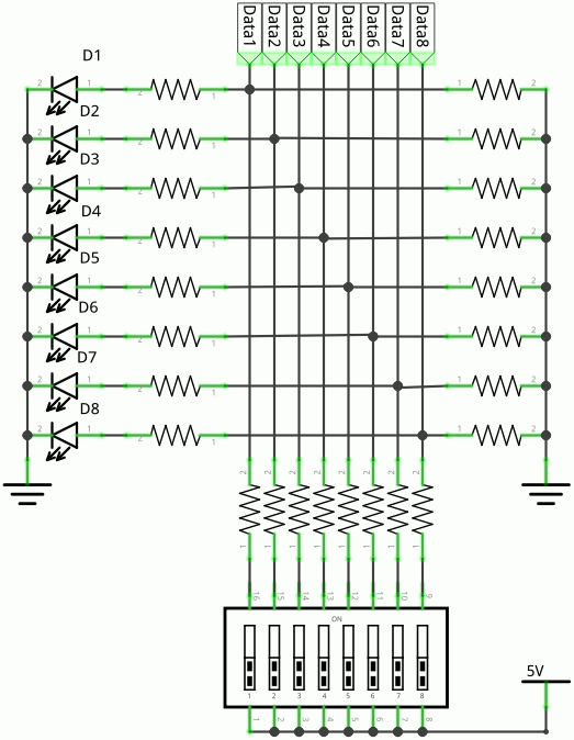
For this project I sourced some alternative rocker switches that could more easily be toggled by hand but they were all SPST ones so using them required pull-down resistors, as can be seen in the schematic fragment below.
Each switch circuit is wired this way so if one of them is accidentally left closed when the output-enable of the EEPROM is asserted there won't be a short-circuit to Vcc when a data bit is zero.
Address switches
The intention was to use push-button toggle switches for all the address bits but there was not the space for this on the selected prototyping board so instead only the six lower bits use them and the upper seven page address bits are set via a DIP switch. This DIP switch is the same type used for the data bits so pull-down resistors are also required here to avoid any floating address bits; these are not required for the push-button switches since the latter are double-throw and hence have a connection to both Vcc and ground.
List of components
Unusually almost all the components used are ones that were sourced this year, so the list of parts includes everything used to build the circuit; in contrast with the previous EEPROM programmer logistics meant I lost track of which stock the components were drawn from. Since my tracking of component stocks fell apart over the last two years I now place higher importance in recording part numbers here in articles rather than in my stock database. With the exception of the ZIF socket all components were sourced from Farnell although some of the items are ones that I have restocked from Mouser.
| Component | Manufacturer | Part number |
| Zero-force socket | n/a | |
| Prototyping perfboard | Multicomp | MC01008 |
| 2-way receptacle | 2212S-02SG-85 |
|
| 5-volt power regulator | Texas Instruments | UA7805CKCS |
| Through-hole Red LED | Kingbright | L-113IDT |
| Tactile button (Red) | TE Connectivity | 1825910-7 |
| Tactile button (Black) | FSM4JH |
|
| 1kΩ protective resisitor | CFR16J1K0 |
|
| 10kΩ pull-up resisitor | Multicomp | MCF 0.25W 10K |
| 8-way SPST DIP switch | Greyhill | 76SB08ST |
| DPDT toggle button | Alps Alpine | SPPH410100 |
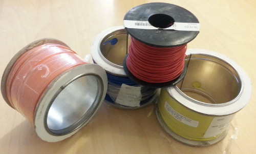
| Blue hookup wire | Condorcia Technologies | EW1/0.6BLU100M |
| Orange hookup wire | EW1/0.6ORG100M |
|
| Yellow hookup wire | EW1/0.6TYELL100M |
|
| Red hookup wire | n/a | |
| Standoff | Duratool | D01495 |
| 3M steel nut | TR Fastenings | M3-HFST-Z100 |
Buttons & switches
Tactile switches are one of those components that until recently were best sourced from E-Bay but I found that Farnell had started stocking them at reasonable prices, and I much prefer the predictability of specialist component vendors. I really wanted to use some double-throw DIP switches rather than rely on banks of pull-up resistors but it was hard enough to find ones that were mechanically suitable without worrying about what they were like internally. These are the sorts of things that in the past meant a trip to Maplin but these days it is the hit-and-miss of just buying in a large number of samples.Choice of prototyping board
Originally I had planned to use some larger prototyping board such as the Alps AlpineSPPH410100 but in the end I opted for a Multicomp MC01008 I happened to find in my most recent stock-take, the main reason being it having bolt-holes for attachment of standoffs.
Having tried out many different prototyping boards over the years and I feel the size of this board is about right, being the same as the MC01010 integrated circuit board I have historically favoured.
I have more or less given up using strip-board because the need to plan out track cuts is a pain, and when I do load up some software in order to design the layout I usually feel I am better off using KiCAD to design an actual PCB.
Decent wire
Back in 2017 I bought a reel of pure copper solid-core wire from Maplin and this stock of wire has been by far the best I have ever used; part of the problem is not knowing what its specifications actually were and since then other brands I have bought have been hit-and-miss. For a long time I used a stock of Alpha Wire which was bought from Digi-Key a while back, and being 26AWG it is quite nice for use with perf-board since it is easy to wrap it around pins with tweezers, although it also has a tendency to break when used with automatic wire strippers. In an effort to run down my Wirecard account one of the things I bought not that long ago was some reels of Concordia Technologies wire, which so far feels the closest thing to my original Maplin wire that I have managed to source for a reasonable price.
Remarks
My original intention was to hold off building this circuit until I had sorted out some personal issues, but I decided to bring it forward as well as simplifying it by using DIP switches instead of more individual push-buttons. Building circuits such as this on prototyping board is as much about process as it is outcome, and with the automated EEPROM programmer fresh in my mind I decided not to hold off any longer. The one down-side is that I am uncertain how many future projects I can think of with that are not just variations of things I have done in the past.