LED display (part 1)
20 July 2017The notional aim of this project was to create a small LED display capable of showing messages, although in practice this was really a multi-attempt crash course in soldering, and this article is really about what I learned from the process. For a long time I have had a soldering iron (and somewhere a small amount of old lead solder), but soldering was something that I did about once every 3 or so years, and I was certainly not versed in correct techniques for soldering stripboard — I did so some electronics back in secondary school but that made use of solderless blueboard. This first part covers the creation of the LED grid alongside the required protective resistors, as actual control of the LEDs will be covered in a future article.
What got my interest in this project is the realisation that driving all LEDs in a display array from a microcontroller is simply unfeasible as few (if any) have that number of output pins, and being on an early-morning train with nothing else to do I thought about how it could be made practical. Thinking was generally around the area of updating batches of pixels so that the microcontroller would only need enough pins for the batch size and addressing the individual batches, and eventually I remembered stuff about D-type latches. It morphed into a practical project when I managed to source some 8-bit latch bank chips for about 50 cents each. The attraction of the project was that the bulk of the work would be circuitry rather than firmware programming.
Practical LED arrays
Actual LED displays use a matrix system where an individual LED is lit by powering its associated row and column pins, but if both multiple rows and multiple columns are switched on, it is ambiguous as to which individual LEDs should be lit. To get around this, the normal trick would be to blink each row at a rate sufficiently fast rate that to human eyes it looks like they are all being lit at the same time. I found some 5 by 8 LED dot-matrix display units, but felt that just a single one would be a programming-dominated project best done in a simulator, and at €7.55 each (for order under 10 units) they were that bit pricey to use many of them as part of a learning exercise. More recently I did manage to obtain some 5x7 LED matrix units that were on clearance sale, but for the time being I'm keeping them as stock rather than starting afresh.The first attempt
For a first time soldering a circuit onto stripboard I think I got quite far, but ultimately it was the wiring that made me abandon it. It was multi-stranded wire of a slightly excess thickness which in itself was asking for trouble, and I suppose was the type of mistake to be expected when learning stuff like this with minimal guidance. With only one and a half rows of LEDs wired up keeping a clear view of the LEDs was already difficult, so I decided to cut my losses and go back to the drawing board. Pity really as testing showed no faults, but I also felt that desoldering the existing wires and putting more suitable solid-core ones in would most likely dislodge things leading to more pain.

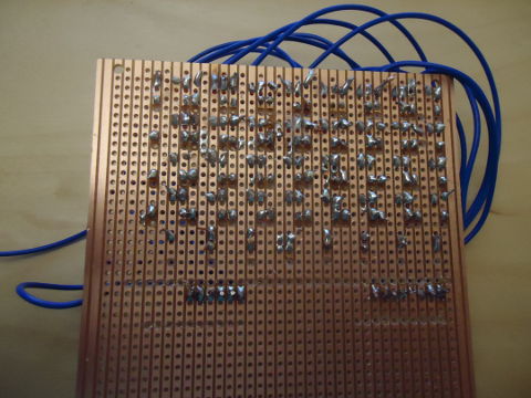
As for the underside — basically a mess. A few of the solder joints are very good, but most have at least one thing wrong with them, the most common issue being the number of steep angled wire remains. There is also one or two places where the copper track is on the verge of disintegrating, and there is one bridging that was fixed by drilling out a track rather than re-soldering. The density of soldered holes was probably asking for trouble given this was the first time I had ever soldered something to strip-board.
Second attempt
This time round I decided that the LED power leads should come in from behind, in order to maintain a clear view of the LED array, which meant meant soldering them directly to the LED anode (positive) wire. I put in sheaths in place to cover the bare metal, and in the longer term would have applied a heat gun to shrink them into place. The only soldering under the LEDs was for the cathode (negative/ground) connections, so there was less worry about short-circuits developing. I also used single-core wire which was much easier to solder into place, and I grouped resistors in their own ban rather than next to the LED they were current-protecting. The leads on the resistors were somewhat thin so tended to bend too easily, so I now have a preference for ones with leads of around AWG 22-24.
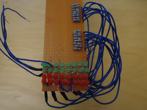
Alas, more basic mistakes. The first was connection of all the LED ground tracks together, which really should have been done before putting the LEDs in. The other more critical mistake was not making the leads long enough so that I could place all the resistors down the same side of the board. At this stage I had thought about making this into an LED & resistor only daughterboard, but I could not find a suitable connector that would straddle the dead holes down the centre of the board. Less critically some of the LED anode wires had become detached, and although these would have been easy to fix being all in the final row, the LED backplane was nevertheless a thick forest and repeated bending of the wires would eventually cause one to break.
Third attempt
This time round I made more of an effort to make the design & building process more systematic, in addition to rolling in some of the experience I had gained with the previous two attempts. Having spent my professional life mostly in software such a “waterfall” model is a bit of a culture shock, but in electronics the inability to go back and change stuff requires it.Cost control
By this stage it had also become obvious that the most expensive component by far was the stripboards, with the 9cm-by-29cm and 10cm-by-16cm Veroboards together costing €23. Looking around I found some 10cm-by-10cm (38-by-37 hole) boards that were under €3, but anything even slightly larger than this meant a disproportionate increase in cost. I decided to adopt this board size as a standard and ordered in a stock of them. Apart from the wires this time round all components were ordered online rather than doing another run to the local electronics store.Design phase
I laid out the entire board in Fritzing, which is an electronic package I will discuss below. The original intention was to have 5 rows of LEDs, but there was not the horizontal space for a 5th resistor bank, and as it turned out there was not the space to have the D-type latches on this board either. Given how much effort was spent just getting a matrix of resistor protected LEDs setup, I was happy to make this part its own self-contained board, and since “debugging” (no idea if electronics has its own equivalent term) of electronic circuits mostly involves shoving in LEDs having a load of pre-protected ones is useful in its own right. In any case this is what it looked like in Fritzing:
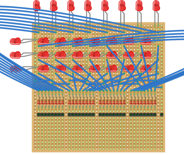
Maybe I should have dropped the 8th column of LEDs and used more of the signal tracks to connect the LEDs to the resistors, but I would have still needed a lot of wiring to rearrange the column-major ordering into row-major that I would require of the pin sockets. Doing bit-rearrangement in firmware would be a bit of a nightmare.
Drilling out
Although I did not follow the plan exactly, I was able to drill out with confidence the entirety of the stripboard before I started soldering, knowing that all the strip cuts would be in the right place. This is easier than cutting strips with the clutter of existing components in place, and also a lot quicker. The one pain is that Fritzing shows the tracks on the same side as the components rather than the underside, and for stripboard have not found any options to switch to the latter view, so the cutting layout needs to be flipped.The completed board
I had reverted to putting the LED power wires on the front, but this time I (mostly) used AWG38 (about 0.1mm) wire to attach the LEDs to their protective resistors. Probably should have used surplus lengths and then bundled them together at the sides, but learning is all about mistakes. At least this time round I got as far as putting everything into place.
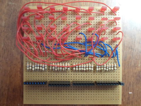
I was caught out by some of the lane holes not cutting across the entire signal lane, which resulted in some of the protective resistors being short-circuited. Result: Burned-out LEDs. I managed to replace two of them, but in the process of desoldering damaged one of the signal lanes, and the remedial soldering work didn't give a good electrical connection. Upshot is that I completed the board, but three of the LEDs in the second-from-bottom row are non-functional.
Lessons about soldering
There are a lot of guides to soldering out there, but what you have to figure out for yourself is how it all comes together. The basic soldering manoeuvres are easy enough to learn, but preparation is also key — things such as correct materials, component placement, and order of doing things. Looking back at the three attempts at building the circuit, these are the main things I realised in the process:- Avoid re-visiting areas
- Soldering more stuff into an area already surrounded with components is a recipe for trouble, both due to the possibility of screwing up previously soldered components, and because I suspect it subjects localised areas to more thermal cycles than they are really intended to withstand. It is better to do a single pass over the whole stripboard, rather than hopping around it.
- Separate out components
- With the first attempt each LED along with its protective resistor and its signal wire formed a roughly G-shaped layout, and keeping track of what should be where was a complicating headache, both when soldering in and when testing with probes. In contrast separate homogeneous rows of components means far less to think about at once, which means less scope for mistakes and an ability to get things done a lot faster.
- Use single-core wire
- Typical multi-stand wire is asking for trouble. It is difficult to thread through holes, keeping it in place to solder it properly is tricky, and all too often loose strands get flattened into places you don't want wires going. Still single-strand wire of around AWG22 is the wire to use as its stiffness makes it easier to keep in place during soldering, and it is easy to remove all surplus length afterwards.
Fritzing PCB software
Not sure how I stumbled across Fritzing, but it is software that allows the laying out of electrical circuits. I had come across various noises about it not being particularly good, and it certainly has its fair share of rough edges, but it is free and once used to it seems to do a half-decent job within certain limits. For doing basic circuit layouts on stripboard it is good enough to work out how much space is needed and where track holes need drilling, but some caution is needed as some components such as the LCD display have pin outs that disagree with part specifications.The down-side is that Fritzing classes itself as beta software, and in some areas it seriously shows. The current way that new components can be made is both incomplete and nowhere near properly documented — as far as I can tell if you want to actually create anything, you have to edit SVG files by hand as stuff like pin position cannot be done in Fritzing itself. Elsewhere there are also hall-marks that internally Fritzing uses brute-force algorithms — it gives a performance warning about stripboards with more than 2,000 holes, and by warning it really means performance going off a cliff edge. 1,400 holes (38 by 37) had no problems, but I noticed performance issues with a board with 1,700 holes (38 by 45), and I ended up killing Fritzing rather than waiting for it to expand a stripboard to 2,090 (38 by 55).
In passing I've seen EAGLE mentioned as the go-to program the PCB design, and to my knowledge it is now be made by the same people who made AutoCAD. Problem is that it is one of those pieces of software that uses subscription-based licencing, and it looks like it switched to this business model earlier this year. I dislike this type of vendor lock-in in principle, even though I suspect the subscription fees are of good value for those who do a lot of this stuff.