NXP USB try-out, take 3
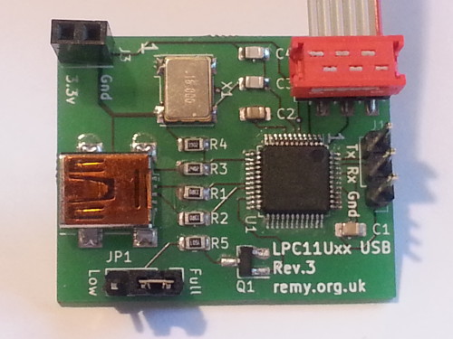
10 October 2020For some time getting true USB connectivity — rather than using an USB converter chip as a bridge between a desktop computer and on-chip TTL-level RS232 pins — had been the last remaining thing left on my bucket-list of ARM firmware programming for some considerable time. However it has not been an easy process and the PCB presented here is an intentionally minimalist LPC11Uxx USB mini-evaluation board intended as a bare-bones platform for the development of the required USB firmware.
Although I could see no apparent design fault with the previous revision of the host board only one of the three I had reflow soldered were in a usable state, and for better or worse decided to design a new one rather than order more of the previous design.
Circuit design
The circuit is a simplification of the previous design with the explicit intention of requiring a smaller PCB that retains only the bare essentials needed to demonstrate USB functionality. This new revision completely removes the I2C and GPIO connections as well as the external power tap, as none of these were even populated with the previous revision of the PCB. From the outset I decided that I would open-source the hardware design to compliment the firmware, the latter of which I will write up and release when I have finally got it fully working.
USB interface sub-circuit
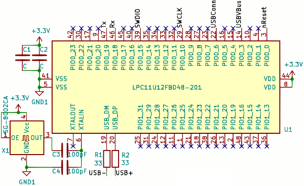
For reasons I don't know the microcontrollerUSB_VBUS pin that is used to detect USB power is only 5-volt tolerant when the chip is powered up, so resistors R3 & R4 are used as a voltage-divider to reduce the USB power to a safe level.
A USB device connection is detected by a host computer by one of the USB data lines being pulled high — the USB- line for a low speed (1.5MBit/sec) device and USB+ for a full speed (12MBits/sec) device.
In this circuit the 1.5kΩ pull-up is controlled via a PNP transistor connected to the microcontroller's USB Connect pin.
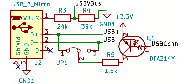
In past revisions each data line had its own pull-up and I left one of them unpopulated but for this revision I decided to include selection via a jumper. The grounding capacitors were also removed because I saw no benefit of having the the decoupling, at least with the low-noise setups I was using for testing.
Programming connector
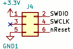
Programming is intended to be via my custom-made adapter and the connection is via a 6-pin Micro-MaTch connector for which the wiring is shown below. This is an adapter I made because I thought the price of mini-IDC receptacles was excessive, and having used the interface on other circuits of mine I have since made the adapter's PCB design files open-source. The previous revision used a standard-sized 10-pin IDC connector which I felt was too big.
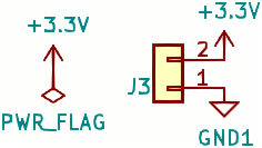
Power supply
In order to save space I removed the voltage regulator and barrel connector the previous revision had, replacing it with a simple 2-pin receptacle intended to take power from mini power boards. The first revision of the circuit had one of these but it was used to self-power the board when being programmed rather than being for actual use. Had I been aware of Aisler's changed price model I most likley would have kept the on-board regulator due to there no longer being a big cost saving. ThePWR_FLAG symbol is part of KiCad's error checking.
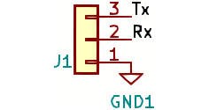
RS232 header
TTL-level RS232 was how I provided a channel for status messages in previous revisions and this is carried over into this circuit. Since I ordered in a FDTITTL-RS232-RPI “Raspberry Pi” TTL-level serial adapter that plugs directly onto header pins this has been a very convenient interface, although I have not been consistent with pin ordering and for this circuit I put the receive pin in the middle.
Non-functional low-speed USB
One of the reported advantages of low-speed USB is that it does not require an external clock source, and in part due to the high fault-rate with the building of the previous revision of the board that meant, I decided to make the speed user-selectable via jumpers rather than requiring the removal and re-soldering of a resistor. It seemed a sensible idea given that this board is intended specifically for the task of USB firmware production. However I recently discovered that contrary to what is stated many times in the data-sheet, such as Table 19 in Section 3.5.13 and a bullet point in Section 11.4.7, theLPX11Uxx does not actually support low-speed USB.
The up-shot of this is that this revision has no real advantages over the second revision of the board, and due to it having on-board power I had more copies of the latter fabricated in order to see what JLC-PCB are like. I have more or less gone off Seeedstudio and so far it seems that JLCPCB are a better service for the quantities I prefer to get, but I digress. The first revision is completely useless since it is also unable to utilise full-speed due to clock accuracy, but at least I know that its basic design is sound for USB bus power.
Bill of Materials
This circuit was constructed back in August while I was in the UK so like other circuits I made around the same time all the components were ordered specially for the circuit from Farnell UK, and these are listed in the table below alongside PCB footprint codes and ordering details. I normally omit cost due to using existing stock bought in bulk but in this case made an exception since they were all bought at the same time. In this case, as it is in many other instances, the vast majority of the cost is the PCB itself.
| PCB | Description | Manufacturer | Part number | Order code | Cost |
U1 |
Microcontroller | NXP | LPC11U12FBD48/201 |
2314755 | £1.34 |
X1 |
16MHz oscillator | Multicomp | MCSJK‑6NC2‑16.00‑5‑B |
2854364 | £0.84 |
R1,R2 |
33Ω resisitor | MCWR08X33R0FTL |
2447640 | £0.58 for 100 | |
R3 |
24kΩ resisitor | MCWR08X2402FTL |
2447613 | £0.52 for 100 | |
R4 |
39kΩ resisitor | MCWR08X3902FTL |
2447646 | £0.58 for 100 | |
R5 |
1.5kΩ resisitor | MCWR08X1501FTL |
2447592 | £0.54 for 100 | |
C1,C2 |
0.1μF capacitor | MC0805B104K250CT |
1759166 | £2.76 for 100 | |
C3,C4 |
100pF SMD capacitor | Kemet | C0805C101JAGACTU |
2896861 | £1.32 for 100 |
Q1 |
10k/47k PNP transistor | ON Semiconductor | MMUN2114LT1G |
2317632 | £0.10 |
J2 |
USB Mini Type-B | Wurth Elektronik | 65100516121 |
1642036 | £0.95 |
J4 |
6-pin receptacle | AMP/TE Connectivity | 2178711-6 |
2473358 | £0.68 |
| n/a | Jumper | Multicomp | MC-2228CG |
2834673 | £1.41 for 50 |