NXP USB try-out, take 2
02 August 2020In the past when I required a USB interface, which in practice has meant creating various USB-I2C adapters, I have used a USB-RS232 adapter chip and written the firmware to use RS2323. However native use of a USB interface on a microcontroller has been on my to-do list since last summer, in short due to curiosity in response to a project I did as part of my day-job, although the relative complexity of the task meant that it got pushed to the very end of my project back-log. I only made serious head-way in writing the firmware for USB communications earlier this year, and this article presents a circuit based around an NXP
LPC11U24 Cortex-M0 microcontroller which was made as a platform to finish off this firmware.
The previous USB try-out board was functional enough to use for USB firmware development but it had it had short-comings — the main issue was relying on the internal oscillator which simply did not have the accuracy required for full-speed USB. Although it could still have been used for low-speed USB, I instead decided to bring forward creation of a second-generation board that is self-powered rather than drawing power from the USB bus.
The circuit
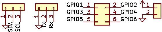
For better or worse I decided to use theLPC11U24FBD48 which is the 48-pin QFP model because KiCad's built-in library did not include a schematic symbol for the 33-pin QFN variants. While using an off-the-shelf symbol avoided a major source of mistakes, I dislike its choice of pin groupings — as shown in the schematic fragment below it orders pins by GPIO port number, whereas I prefer them to be ordered by pin number.
I find that in practice schematic layout sometimes has to make choices based on where pins are on the physical package, in this case most obviously with the GPIO connector, so I prefer symbols that approximate the physical chip.
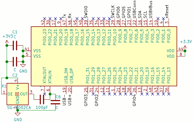
The external oscillator is attached by an AC amplitude attenuator made from two capacitors, and based on the formulae given in the data-sheet using 100pF for both should reduce the maximum 3.3 volts to 1.65 volts, which is safely below the maximum 1.8 volts the XTAL pins can tolerate. Bypass capacitors for the power supply pins are also included although more often than not I do not populate them when it comes to soldering the board. The rest if the circuit is described in the sub-sections below.
JTAG
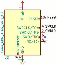
The KiCad 5 symbol library includes a symbol for the programming connections, which is shown below, and although it is rather big for my liking it nevertheless removes a potential source of mistakes compared to using a generic connector symbol. Since the combination of OpenOCD and the OlimexARM-USB-TINY-H programmer I have does not support full JTAG for LPC11(U)xx devices I only provisioned for SWD (serial wire debugging).
For the physical connection a 2.54mm pitch 10-pin IDC connector is used.
Power supply
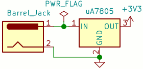
Rather than drawing power from the USB bus this circuit is intended to be powered via its own on-board power supply, which is detailed in the schematic fragment shown below. For convenience the on-board regulator is supplied via a barrel connector, as shown in the schematic below, so the circuit can be used stand-alone rather than requiring an external regulator such as my power daugher-board.
USB connection
In the previous circuit the pull-up connected to the USB data line was hard-wired but for this revision it is placed under firmware control via the USB Connect pin, using a pre-biased PNP transistor as a solid-state switch. In addition the USB Vbus pin is used to detect a USB connection by sensing voltage on the USB 5-volt wire — the latter required since this circuit does not use USB as its power source, and hence needs a way of knowing whether it is connected to a USB host. The schematic for how these two pins are connected to the USB port is shown below. Note that only one of resistorsR2 and R3 is supposed to be installed, as which data line is pulled up deetmines whether the device is low-speed or full-speed.
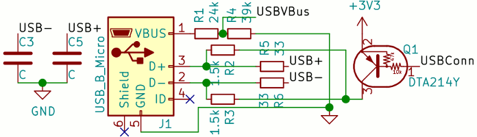
The voltage-divider is required because the USB VBus pin is only 5-volt tolerant when the microcontroller is powered up, which is not guaranteed for a self-powered circuit. Recommended values for the passive components are given in NXP Application Note 11392.
Serial & GPIO headers
Pin headers for both TTL-level RS232 and I2C are standard things I include on microcontroller host circuits such as this one, as they are the two communication interfaces a typically use. Whereas the I2C is intended for potential future projects, The RS232 connection is to be used as a debug information side channel to aid firmware development, particularly with the omission of on-board LEDs. Some GPIO pins were something I added at the last moment as there was space to squeeze in a 6-pin MicroMatch connector, although I seriously doubt they will ever be used.
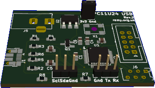
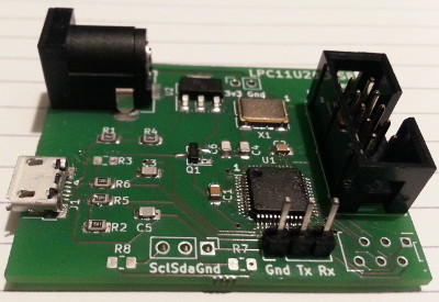
Board production
For this board I used Aisler who are relatively expensive but the turn-around time they offer has been getting noticeably faster — I ordered the PCB on a Saturday, it was shipped on Wednesday, and was in my mailbox on Monday. Due to circumstances at the time I needed to get the PCB fabricated and reflow soldered to a rapidly approaching hard deadline, although as it turned out it would not be the last PCB I reflowed prior to vacating the property.
Components
Even though I have some custom written software for maintaining a component database, in practice more often than not I instead look back at past articles when trying to remember what components I used for a particular task. Because of this I now include a bill of material summary as part of project write-ups, and this is presented in the table below. It lists all components together with part numbers and vendor order codes. I have sometimes in the past also included pricing information, but have given up doing so because of all the caveats the information required.
| Description | Manufacturer | Part number | Vendor | Order code | |
| ARM Cortex-M0 | NXP | LPC11U24FBD48 |
Farnell | 2069972 | |
| Mouser | 771-LPC11U24FBD48401 | ||||
| 3.3v 16Mhz Oscillator | Multicomp | MCSJK-6NC2-16.00-25-B |
Farnell | 2854364 | |
| 3.3v power regulator | Texas Instruments | UA78M33CDCYR |
discontinued | ||
| Mouser | 595-UA78M33CDCYR | ||||
| 10kΩ/24kΩ PNP transistor | |
Farnell | 2317632 | ||
| Resisitor | 33Ω | Multicomp | MCWR08X33R0FTL |
2447640 | |
| 1.5kΩ | MCWR08X1501FTL |
2447592 | |||
| 24kΩ | MCWR08X2402FTL |
2447613 | |||
| 39kΩ | MCWR08X3902FTL |
2447646 | |||
| Capacitor | 100nF (0.1μF) | Kemit | C0805X104K5RACTU |
1414041 | |
| 18pF | Vishay | |
|||
| 100pF | Kemet | C0805C101JAGACTU |
2896861?? | ||
| Micro-B USB socket | Amphenol | 10103594-0001LF |
2293752 | ||
| IDC flashing socket | Multicomp | MC-254-10-00-ST-DIP |
2843527 | ||
| MicroMatch socket | TE Connectivity | 2178710-6 |
2473349 | ||
| DC barrel jack | Cliff Electronic Components | FC681465P |
1854512 | ||
| 2-way receptacle | Multicomp | 2212S-02SG-85 |
1593458 | ||
| Pin header | From strip bought off E-bay | ||||
Farnell claims that the LPC11U24FBD48/401 (48-pin LPQFP) is no longer manufactured but this is at odds with what other vendors are currently stating.
Farnell is still my preferred supplier but in the last few months I have noticed a much increased incidence of them either not having items in stock, or items being discontinued.
PCB placement
Unusually I decided to reflow-solder almost all the components, so I needed to put together a table of what component and value to put on each foot-print, and this is replicated below. In the past I normally only reflowed the most complex chip and hand-soldered all the other mostly passive components, which meant boards were completed on an ad-hoc basis. However using reflow for all components requires that bit more forward planning, as everything is done in one go.
| Landing | Value | Description |
| C1, C2 | 0.1μF (100nF) | Power bypass |
| C3, C5 | max. 50pF (0.2nF) | USB edge rate control |
| C4, C6 | 100pF (0.1nF) | AC attenuator |
| R1 | 24kΩ | USBConnect voltage divider |
| R4 | 39kΩ | |
| R2 | 1.5Ω | USB speed select pull-up |
| R3 | not used | |
| R5, R6 | 33Ω | USB termination |
| R7, R8 | 10kΩ | I2C pull-ups |
| J1 | n/a | USB socket |
| Q1 | Transistor | |
| X1 | Oscillator | |
| U1 | Microcontroller |