5-volt mains adapter
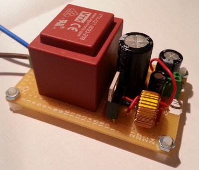
11 September 2020This circuit is a power adapter that converts 240-volt mains AC into 5-volt DC and is derived from designs I used in two other recent circuits of mine. It makes use of a step-down transformer and bridge rectifier to obtain an unregulated 9 volts which is then passed to a Buck converter to obtain the desired 5-volt DC. Much of the investigation in this mini-project was trying out new components rather than new designs, and the result is shown below.
Circuit design
The circuit is basically the transformer & rectifier sub-system from my solid-state AC control board but with the regulator replaced with a modified version of my 5-volt Buck converter circuit — in the latter case the changes are use of components of different ratings. Compared to the Buck converter circuit I built previously I replaced the recommended rectifier diode with a lower-rated fast recovery diode because the former would not fit through the holes on prototyping board, and I opted for a toroidal inductor intended for power supplies rather than the choke I used previously. The complete schematic of the new circuit is shown below.

The 3300μF smoothing capacitor is quite likley overkill for removing ripples from the rectified DC but I did not have many alternatives in stock that had the required voltage rating and in any case I thought the less ripple the better. I also included a parallel 100μF bypass capacitor because I was unsure whether the larger capacitor by itself would be capable of dealing with any higher-frequency transients.
Circuit construction
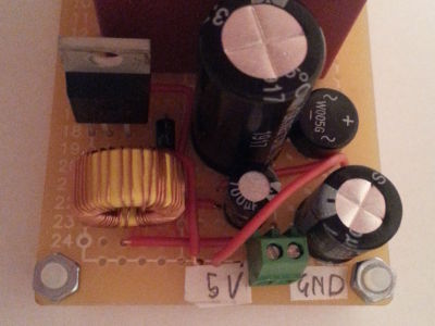
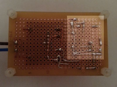
This circuit uses up a almost all the space available on the prototyping board, and most of the components are tightly packed into a small proportion of the board real-estate, as is best seen from the top-down pcite shown below. One thing that surprised me was how much of the circuit connections were done on the solder side of the perf-board, and it was only quite late in the soldering process that I started to add fly-leads.
In hindsight the layout looks pretty optimal with ground connections all being along an L-shaped spine highlighted in the picture below. All I can think of is maybe swapping the positions of the 3300μF smoothing capacitor and the 1000μF switching output capacitor, but with such a tight fit already I could not tell without actually trying a rebuild.
List of components
A few of the components I used for this circuit are are old stock that I bought as long as two years ago so I have no idea if they are still stocked or even manufactured, so this time round I have omitted vendor order codes from the itinerary of components shown below. Although price information is not included I noticed that by speccing components for a current draw substantially lower than the 3 amperes the Buck converter typical application circuit assumed, components were substantially cheaper. For instance while the MulticompMCAP105228050A-101MU toroidal inductor which is rated at 500mA is about 68¢ the 4.3-amp MCAP109020040K-101MU comes in at €2.30.
| Component | Manufacturer | Part number |
| 72x47mm perfboard | Multicomp | MC01007 |
| 240v to 9v isolation transformer | Vigortronix | VTX-121-3023-209 |
| Bridge rectifier | Multicomp | W005G |
| Buck switching regulator | ON Semiconductor | LM2576T-005G |
| 100μF capacitor | Multicomp | MCGPR25V107M6.3X11 |
| 1000μF capacitor | MCKSK010M102G13S |
|
| 3300μF capacitor | MCKSK025M332I25S |
|
| Fast recovery diode | BA157 |
|
| 100μH toroidal inductor | MCAP105228050A-101MU |
|
| 2-way 30AWG terminal block | TE Connectivity | 282834-2 |
| 2-way 26AWG terminal block | Multicomp | MC000034 |