TM1637 button input
24 May 2026The previous investigation of the Titan Microelectronics
TM1637 LED driver chip was abortive as it did not get as far as attaching a compatible LED display, but now with such a component and some spare time at hand this unfinished business can be completed by driving a full display rather than just a few test LEDs.
In addition to display output the driver chip is also able to handle input from a grid of buttons which allows for a second round of investigative toying around which is the main goal of what is described here, although to get to that stage needed new hardware and new firmware to be created first.
The LED display and button grid share common wiring so as part of the duty cycle power is sent via the buttons rather than to the LED display anodes, and within this a pulse sequence is used to work out which button is pressed. It is an interesting way to give a display chip a dual-purpose of being able to read lots of buttons, although it is a bit disappointing that the interface does not support pressing multiple buttons at once.
Button array creation
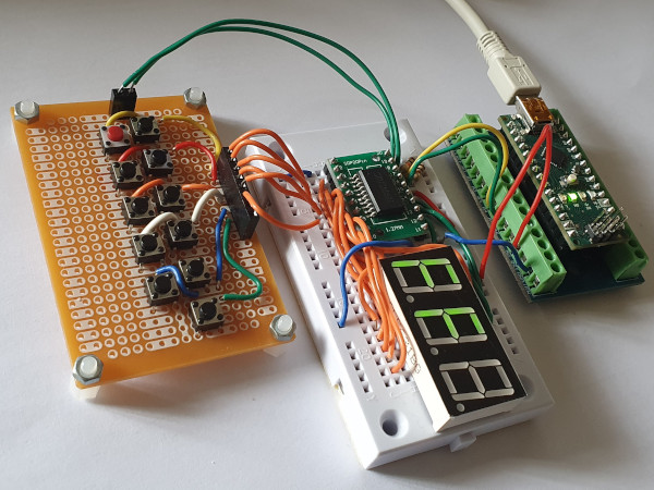
The original intention was to have all sixteen buttons wired up and a twelth button should have easily fitted in, but this circuit was knocked together in an ad-hoc manner and for testing purposes it is good enough. There is a notable difference in quality between the tactile buttons bought from specialist electronics vendors and the ultra-cheap ones bought in packs of 50 or 100, with the legs of the latter being much more likely to bend out of place. For assembly of the button array I used my MaplinN05HW portable soldering iron which worked surprisingly well when the existing AA power cells were replaced with USB rechargable 2600mWh lithium cells.
It is a bit cumbersome to use and would not use it for larger or more complex circuits but in this one was made in my Manchester apartment where keeping a full-power soldering station around is not currently justifiable.
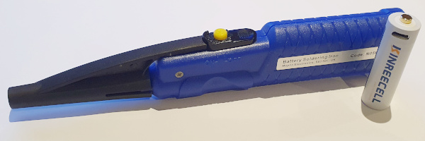
Forget when this portable soldering iron was bought but suspect it was back in 2017.
I only came across lithium power cells in traditional form-factors of AA and PP3 (9v square) late last year so don't currently know how good and/or safe they are, but so far one suspected disadvantage is much faster leaking of energy when left idle due to having active voltage boosting circuitry.
My current stock of traditional AA power cells is enough for months if not years for the few things I use that need them so not in any rush to switch over to them.
Display library rewrite
For experimental purposes I decided to write my own TM1637 library based on the data-sheet specifications due to the off-the-shelf Arduino library only supporting output, and even then having some limitations that were apparent when using it as display unit for the Arduino based timer. Doing a rewrite is also due to a longer-term goal of writing an ARM Cortex-M0 library, as it provides more hand-on experience with the wire-line protocol. Development used the previously deployed off-the-shelf display based on the driver chip as it was a known good as well as being more compact to transport around.
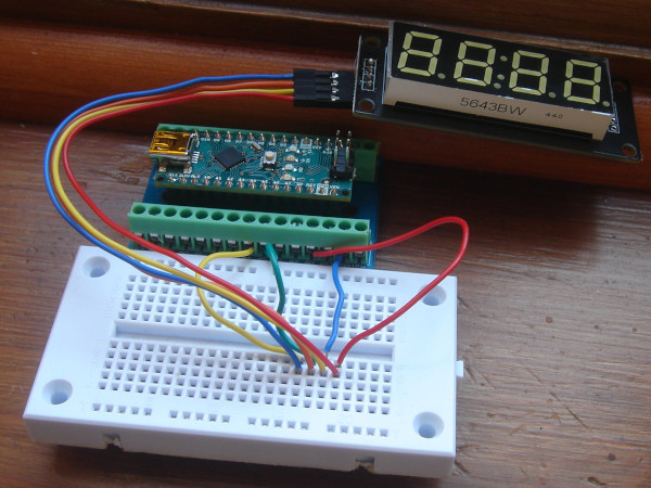
Even with trying to go from first principles starting with I2C specifications, things like using restart instead of stop/start did not work, and aside from some delays being a lot lower or eliminated entirely the bit-banging primitives ended up not vastly different from the off-the-shelf library. Not clear why clock-high pulses needed to be a full 50μS or so whereas clock-low pulses were happy being only 5μS, and the data-sheet itself implies that even the clock-high pulses do not need to be anywhere near this long. Later on it would transpire this was specific to the off-the-shelf units as the standalone TM1637 chips were fine when pulse duration was substantially reduced.
The original idea was to use a LED matrix to show button status but that proved a distraction, so driving a matrix display was spun out into seperate article. Instead a 3-digit LED display was wired up which also had the advantage of using a much smaller breadboard, although the brightness of the display made it hard to read in daylight whereas it was fine under florescent lighting. The purpose of the LED display is to show the code from the button scanning as well as to demonstrate the mixing of button reads and display writes.
Reading the button grid
The bit reading function was basically the bit writing function changed so that the data line was always allowed to go high rather than being pulled down dependent on bit value, and then adigitalRead() of the data line added at the very end after the clock-high period wait had completed.
Other than that the code for reading is the same as writing, as unlike an I2C read where an acknowledgement should be written after a bute has been read, with the TM1637 an acknowledgement is read from the chip for both reads and writes.
With that in place the table below gives the values in hexadecimal which correspond to each botton press.
Presing more than one button at once is not supported as the code is a button identifier rather than a bit-mask.
| SG1 | SG2 | SG3 | SG4 | SG5 | SG6 | SG7 | SG8 | |
| KS1 | 0xf7 |
0xf6 |
0xf5 |
0xf4 |
0xf3 |
0xf2 |
0xf1 |
0xf0 |
| KS2 | 0xef |
0xee |
0xed |
0xec |
0xeb |
0xea |
0xe9 |
0xe8 |
The upper nibble is either 0xe or 0xf (i.e. LSB set/unset) which corresponds to KS1 and KS2 respectively whereas the lower nibble is unique for every button, so if SG1/KS1 is not wired up the top nibble could be masked out.
The data-sheet is confusing in giving the scan codes with the LSB to the left so it considers 1110_1111 to be 0xf7 and as a result at first it seemed that the scan codes listed were wrong, when in reality they matched the values obtained experimentally.
Remarks
The original idea was to use a LED matrix to show button status but that proved a distraction so driving a matrix display was spun out into separate article, and instead a 3-digit LED display was wired up which also had the advantage of using a much smaller breadboard. The down-side was the brightness of the display that made it hard to read in daylight. In hindsight that spun-out article should also have taken on the section on the initial rewrite of the firmware from scratch and left this article to deal purely with button read scanning, as the only useful information it contained as done is the corrected pin-out for a display module that may well be discontinued.This was one of those projects that conveniently broke down into bite-size chunks and it was also easy to transport around the few components needed for each chunk, but it still fell victim to other things including a conference trip overseas taking up time as well as the simple lack of motivation. While the button array was made back in January it was the end of April before any serious effort was put into the firmware library rewrite, and then well into May before the firmware implemented input processing which ironically was done in a single sitting.