Wireless modules revisited
12 May 2024The topic of my Ph.D was medium access within wireless networks so a few years ago a potential project of mine was to reimplement some of those research ideas, but using radio-frequency rather than 802.11 as a base communication layer due to its simplicity. While the project as a whole did not get as far as implementing my research findings instead only getting as far as some basic data framing for a counting system, this in itself was a big step given the limitations of the PIC microcontrollers used to implement the circuits. A switch-over to ARM microcontrollers in order to allow the use of C rather than assembly was in the works but events then got in the way.
The project here is a reimplementation of the wireless counter button firmware on Arduinos, the intention being to revisit issues related to the data frame coding scheme and how it is processed when viewed with a clear mind. This is a clearing away of technical debt and finally switching to a platform much better suited to experimentation, even though the functional outcome is not much different to previously.
The radio hardware
Back when conceiving the idea of the wireless buttons project the starting-point was off-the-shelf transmission and reception modules that implemented the most basic OOK (On-Off Keying) amplitude modulation and the ones eventually settled with were the RF SolutionsQAM-TX2-433 transmission module and the QAM-RX10-433 receiver module, both of which are self-contained and operate in the 433Mhz band.
A high or low on the input/output they provide corresponds directly with the presence/absence of a signal which is as simple as things get and it is up to the host circuit to deal with things like timings and data framing.
Later on I made my own RF modules based around the Melexis TH72012 and the Maxim MAX7030 although they were direct implementations of reference circuits given in their respective data-sheets.
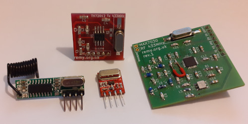
The QAM-TX2-433 transmitter module has a pitifully low baud rate of only 3kHz which is why a 1mS mark/space width was selected for the protocol, whereas the QAM-RX10-433 receiver module has a maximum receive rate of 10kHz.
Fortunately the transmitter module based around the TH72012 can support a baud rate up to 40kHz and the module based on the MAX7030 is bi-directional and supports up to 66kHz.
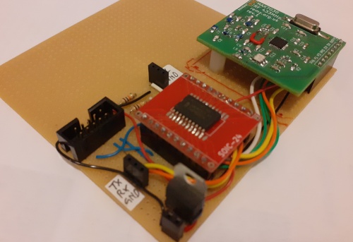
At the time a prototype host board for the latter module based around an NXP LPC1112 Cortex-M0 was built and tested but never saw developmental use.
Receiver reimplementation
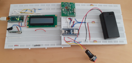
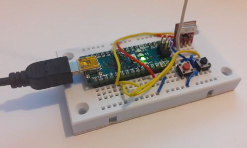
The starting point was to reimplement the firmware on hardware that is more suitable for experimentation so the existing counter transmitter was used as a test reference while a new receiver was built around an Arduino Nano. Whereas thePIC16F630 based transmitter was spot-on in its implementation writing the reception firmware on a PIC16F1823 microcontroller involved a lot of tricks that are a big distraction from the underlying algorithm, and even at the time I considered using an ARM Cortex-M0 microcontroller instead.
The goal here was a from-specification reimplementation rather than a white-box clone with the intention of highlighting the edge- and corner-cases in the protocol.
Being five years ago I cannot remember how robust the original reception unit was but it certainly had tweaks that were not covered by the project write-up that was being used as the specification. No longer up to speed with PIC assembly very little time was spent going over the old code because it had a lot of design decisions that were driven by hardware limitations that no longer apply, but it is probable that some of the sanity checks mentioned below were in the original reception code.
False signal locks
It was possible for noise to fool the prefix detection but it was also noted when this does happen the vast majority of the time it corresponded to a mark width under 250μS and often under 100μS which is significantly below the typical 750μS mark width. Low-pass filtering the transmission prefix using a fixed threshold was effective but longer-term this would cause problems with higher bit-rates and in any case there are still some false signal locks. Much experimentation was done with aborting frame receptions where the mark or space width deviates too far from those extracted from the prefix but at times there was the suspicion of false-positives. Noise decoded as the length field tended to result in numbers towards the upper limit of frame size so another check tried out was timeout that aborted the spurious frame read before a genuine frame arrived. General feeling at the time was data check-summing being by far the best thing to catch spurious transmissions, with everything else being hacks that relied too much on empirical thresholds and due to the latter were hence of at best dubious robustness. Ultimately these checks were work-arounds for the limitations imposed by the format of the frame, and further experimentation could be done when the originalPIC16F630 transmitter was replaced with a newly implemented Arduino based transmitter.
User interface issues
A major headache was debugging messages sent out out via a side-channel interfering with the reception process itself, as message transmission introduces a delay that can cause an incoming signal transition to be missed and hence screw up timings. I suspect such side-channel delays may have been a complication when trying to debug USB firmware last year. From experimentation with the particular LCD display used here it is possible to refresh an entire 16-digit line in 868μS which compares to the notional mark & space width of 1mS and one potentially disrupted bit in the transmission prefix is managable. The built-in serial monitor on the Arduino can be cranked up to 2,000,000 baud but the LCD display attached to the receiver does not have this luxury. Ultimately the take-home message is beware of attempts to add observability for the purposes of debugging themselves causing problems.Transmission timing inaccuracies
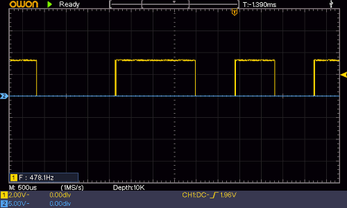
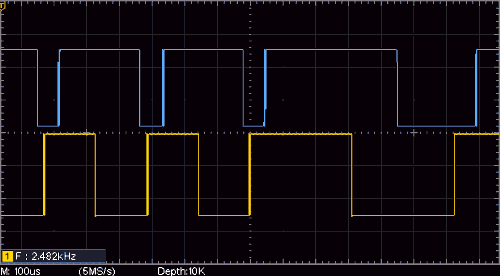
The output from the transmission control is a pulse wave where each mark and space is meant to be either 1mS or 2mS in width and at the time lack of an oscilloscope meant these could not be properly checked. Inaccuracies with timers on PIC microcontrollers was known from drift in long-running tests and it was probable that some prior testing was done using the frequency measurement functionality of a multi-meter, but for whatever reason the accuracy of the timing was not questioned in the article written at the time. Using an oscilloscope the actual mark & space width were both either 900μS or 1800μS as shown on the trace below and these are a significant deviation from expectation considering the internal 4Mhz clock of thePIC16F630 is supposed to be calibrated to ±1%.
The adaptive nature of the reception algorithm is able to cope with this inaccuracy and the main practical effect is an over estimation of distortion introduced by the wireless channel, but it nevertheless potentially invalidates any quantitative reasoning with the circuit.
Fortunately much of the experimentation that would potentially rely on the accuracy of the transmitted signal had already been deferred pending a rewrite of the transmitter firmware, but as noted later the mark and space widths get messed with when transmitted through the radio-frequency channel.
Transmitter reimplementation
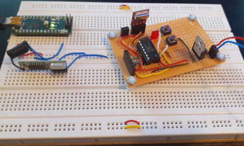
While using the existingPIC16F630 transmitter was a useful reference when reimplementing the receiver it had constraints and issues so in turn the transmitter was reimplemented using an Arduino Nano, which in turn provided more flexibility in experimentation whioch is detailed in the next few sub-sections.
It also meant that the same platform was now being used for both the transmitter and receiver — reimplementing the transmitter using ARM Cortex-M0 microcontrollers was considered but for experimental purposes this did not have any apparent benefit and logistical circumstances of the time were against such an approach.
Signal skew
Even though short mark and space widths in frames are an equal 1mS on transmission they vary between 900μS and 1100μS on reception, with long mark/space widths being the expected double of these values. This skewing of the transmitted wave-form as it passes through the channel was noted previously and has some link with how busy the channel has been. A prior concern was whether long/short thresholds would need to be adjusted over the duration of longer frames so the deltas between signal transitions was recorded and their deviation from the mean is plotted below. As expected received transition spacings do change over the duration of a frame transmission but convergence happens quickly, so there is a case for some sort of threshold adaptation although its effects will be limited to the first few octets.
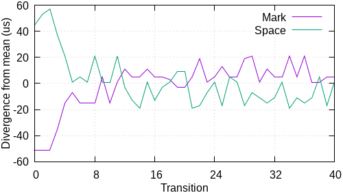
The initial circa ±55μS variation from mean is concerning considering that prefix detection uses a ±50μS threshold, although the variation very quickly tightens up to ±20μS and all this is believed to be down to the reception module self-adjusting. At this point the suspicion was that a two-octet prefix ought to be used so that any adjustment the RF module needs to do is done and dusted before the header bits are reached, and indeed this is what was done later on.
Effective noise filtering
A surprisingly effective way of filtering out noise-induced signal locks is to have a signature byte within the header that is always the same value and in the two-button counter use-case having a single fixed data length fulfilled this. To allow the full range of possible data lengths a dedicated signature byte is used instead which has the value0xaa and this value corresponds to a byte consisting entirely of long marks and spaces, making it intentionally different from the transmission prefix that is almost entirely short transition intervals.
An advantage of this type of approach is avoiding having to use heuristically-chosen thresholds as the latter bring with it a fine balance between false positives and negatives.
In a test run that had a total of 949 noise-induced signal locks 937 were detected by a bad signature which is an error rate of 1.3% false negatives. Of the twelve that slipped through the signature check eight were immediately caught by having the length field duplicated and inverted within the header and the four that got passed the latter were caught by the end-of-frame check. This four in twelve calls into question the value of checksumming header fields independent of the rest of the frame since it corresponds to a high failure rate over a small number.
Cranking up the speed
As an experiment theQAM-TX2-433 module which is limited to 3kHz was replaced with one based around the TH72012 which can do 40kHz, and the transmission interval reduced in order to increase the effective channel capacity.
In practice doubling the speed with a 500μS interval worked but anything less than that had intermittent problems with frames getting corrupted and it was not clear where the faults lay.
What was noticed was the first two marks in the transmission prefix being merged into one which had not been an issue with the QAM-TX2-433 but this in itself had not been a concern since such early transitions were beyond the prefix detection window.
Some probing to work out what was going on was performed but ultimately it was decided to scrap the reception algorithm.
A new algorithm
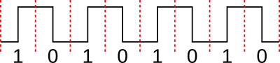
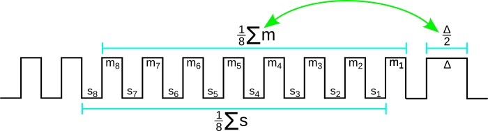
The robustness of the original algorithm was clearly in doubt so the signal-lock logic needed a rethink. Aside from having forgotten how one or two sections of the code operated it also suffered from the highly constrained PIC micro-controllers that hosted the algorithm, so any reimplementation may as well be a complete rewrite from scratch. The same Manhester coding scheme is retained and there was an effort to keep the frame structure unchanged as well, but in the end the frame had to be extended and this new eleven-octet structure is shown below.
| Prefix | Header | Payload | Check | |||||||
| Gain | Gain | Signal | Magic | Length | Sanity | Node Id | Count 1 | Count 2 | Sequence | |
Transmission prefix and signal lock
The transmission prefix has been extended from eight to twenty-four symbols (i.e. three octets) so issues related to the physical layer's gain control are out of the way before the signal lock is obtained. It was initially extended to sixteen symbols but this length of prefix proved tempremental, sometimes working fine and at other times not working at all. Rather than pair-wise comparison of neighbouring marks the lock procedure uses a sliding average of the prior eight marks where the sum of squared deviations from the average have to be below a threshold, and the difference between double this average and the next space also has to be below a threshold. A sliding average average of spaces is also calculated which must also pass a square-of-differences check.
Compared to pair-wise checking of neighbouring marks and spaces this approach disallows a cumulative error between the earlier and later deltas within the prefix check window, and the wider number of samples makes it harder for random values to get passed. After much tweaking and experimentation rthe final algorithm was very effective in filtering out false locks whereas being able to capture most if not all transmissions.
Frame header & payload
The header consists of three parts: A signature, a data payload length, and a header sanity check which is a checksum of the former two octets. In earlier iterations the signature was specifically checked for a magic value and it was retained since it helped debugging. The data payload portion of the frame is unchanged with one octet for a node identity number, and three count octets for the two button press counts and their combined value. The latter is essentially a transaction number of dubious practical value but leaving it in place was the path of least resistance. Although the original plan had been to use a data source other than button press statistics but that has been deferred for a future project.Payload checksum
The final octet tests the integrity of the data and is an exclusive-or sum of all the data payload octets. In the past it also included header octets but the latter now have their own checks and if there was an error there the frame would already be doomed to being messed up.Wireless channel oddities
Back in 2018 it was noticed how the mark and space widths changed during transmission over the wireless channel, although with the reimplemented transmitter and receiver the amount of skew was fairly consistent so some tweaking allowed for very tight thresholds to be used in the signal lock algorithm. However one headache was the relationship between input mark and space widths not being linear with the ones on the output — short widths were reduced by 12% whereas long widths were reduced by 18% — and I suspect these values are specific to the nominal 150μS spacing amoung other factors.
This makes me doubt whether the wireless gain control actually needs the long prefix and that the real trick is working out what consistent but unknown output width is the result of a given input mark or space. However that is something for a future project when multiple bi-directional wireless modules are ready.
Remarks
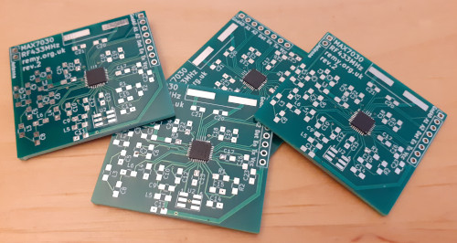
Wireless communications is unfortunately one of those things where the published write-ups are unrepresentative of when the projects were actually done. Trawling old files and emails points towards most of the building and development being done in the last six to eight weeks of 2018, with a hint or two that they were first thought up back in August of that year, but the associated articles were published March 2019. I even found some unpopulated PCBs for a bi-drectional host board that I had forgotten even existed, so this is one of those projects where the whole extent of work done on it and when has been lost to time. In contrast the early-2018 17-segment LCD display was parts ordered to publication in four weeks, and although some of the stuff I wrote back then is cringeworthy it at least documents knowledge progressed.
For this revisit the vast majority of the firmware work was between 30th December and 15th January but it is only now four months later that this article about the whole experience is out, and it could easily have been longer given the chore of bringing things to a conclusion. It only took a day and a half at the start of May to bring the project over the line but competition for my attention was stiff. The longer-term goal is much more than uni-directional transmission of two counter values but for now that is not where my motivations lie, and with a detail or two already having been lost to time it was better to bring a reduced scope project to closure.