Firmware-based night light
12 August 2023In parallel with the hard-wired night light a firmware-based variant was also designed and sent for fabrication in the same foundry order, since the former had a high component count on an oversized PCB. However even though they were originally designed at the same time this firmware version had its own set of problems, both taking far longer to finished than ever intended and even then was never used in the way it was originally designed for. Ultimately the circuit was written off as the effort it was absorbing was not worth the remaining practical benefits and I had other things to move on to.
Circuit design
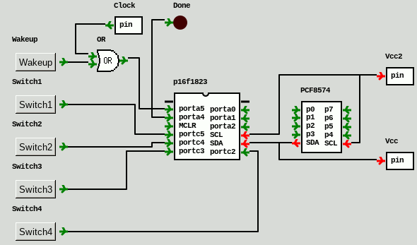
Compared to the hard-wired variant simplification of this circuit was done in two ways: Implementing the counting logic in firmware on a MicrochipPIC16F1823 micro-controller; and replacing the bank of MOSFETs with an I/O Expander with current-sinking outputs.
It was designed in parallel with the previous hard-wired night light and sent for fabrication in the same order, so at least from a hardware perspective it is an alternative implementation rather than a second iteration as it does not take account of things discovered with the “first” version.
Looking back it was really a rush job driven by the low marginal cost of adding extra PCBs to a fabrication order.
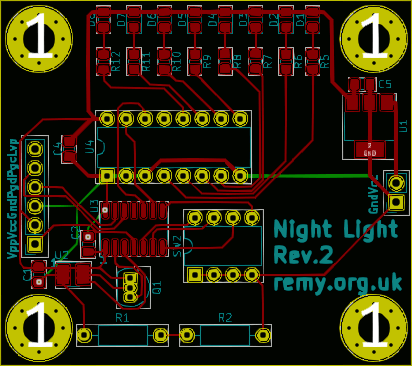
Below is an image of the PCB layout.
Circuit time-keeping
The time-keeping circuit consists of a Texas InstrumentsTPL5110 low-power timer which supposedly consumes only 35μA (at 2.5 volts) and the sub-circuit for it is more or less the reference circuit from the data-sheet and the schematic is shown below.
In the previous hard-wired circuit it was found that over 24 hours the timing would be 10 minutes fast which to be fair is still more accurate than the 1% the data-sheet but over the two weeks the power cell lasted this accumulation was too much, so with this circuit a much smaller delay would be used and some sort of correction applied.
Unlike the hard-wired circuit that had a Resistor-Capacitor network to assert the done signal after a few milliseconds, in this instance it is provided by a microcontroller pin.
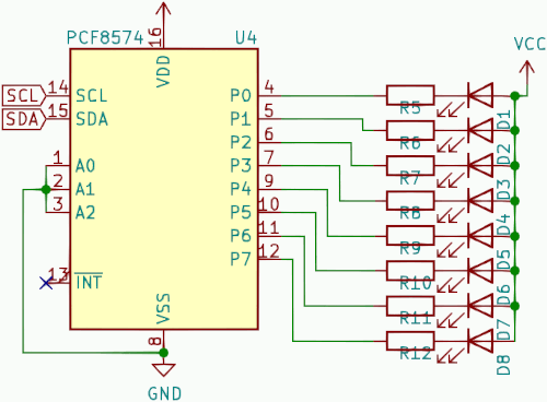
LED current sink
ThePCF8574 I/O expander uses open-collector outputs so it is a direct replacement of the previous N-Channel MOSFET bank which in itself is a large reduction in physical circuit board size.
When the expander is not actively processing an I2C command it consumes a maximum of 10μA and even when operating it itself only draws 100μA.
This is obviously in addition to whatever current the open-collector outputs are sinking and being able to control eight LEDs leaves scope for brightness control and the trying out of different colours.
Rework was required to add in the required pull-up resistors on the I2C signal lines that were accidentally omitted from the PCB design, which is a mistake that has been made a few times in the past.
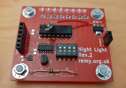
Configuration switches
Previously the configuration switches were on the current path of the LED array but now they are connected to the microcontroller and do not carry any significant power, instead they are just a way for end-users to adjust configuration. The microcontroller has internal pull-up resistors so the switches connect the signal pins to ground and as a result there is no need for external resistors. For better or worse I had decided to keep pins used for firmware flashing dedicated to the programming header and limit the number of switches to four, on the basis that the firmware allows for flexibility lost from having fewer user interface toggles.Circuit power
Provision for a linear voltage regulator was included for debugging purposes because it was unclear how the micro-controller would react to a fully unregulated voltage, and at time of design the expectation was that it would not be required. In practice things were a bit of a pain because the 4.2 volts of a fully charged power cell was above the “absolute maximum” specified for the micro-controller, so in the end a standard 3.3 volt regulator was installed and the board run from the usual 9-volt D-type power cells rather than the intended lithium-ion power. Some supposedly ultra-low dropout linear regulators are at time of writing being sourced but they will be evaluated another time using unused power-pack mini-PCBs recently relocated. A common problem with “low” drop-out regulators is the drop-out voltage not actually being that low and when the drop-out threshold is breached many cut out completely rather than providing unregulated undervolted power so it is better to test them in isolation.
Circuit components
The original intention was to build this circuit on prototyping board using a breakout adapter for the external timer but obtaining through-hole packages of components has become a lot harder over the last year or so, and there are a lot of things that my usual supplier Farnell has to all intents and purposes stopped stocking — I even came across one component that had an expected delivery date of June 2025. Nevertheless below is the list of the main components used in this project although I know for certain some of them have been discontinued by their respective manufacturers.
| Component | Manufacturer | Part number |
| 120Ω resisitor | Multicomp | MC01W08055120R |
| 270Ω resisitor | Multicomp | MCWR08X2700FTL |
| 4-way DIP switch | TE Connectivity | ADE0404 |
| 8-bit I/O Expander | Texas Instruments | PCF8574AN |
| Nano-power timer | Texas Instruments | TPL5110 |
| P-Channel MOSFET | Microchip | TP2104N3-G |
| Blue SMD LED | Kingbright | KPT-2012LVVBC-D |
| Yellow SMD LED | Kingbright | KPT-2012YC |
| Green SMD LED | Kingbright | KP-2012LSGC |
Circuit firmware
By the time the physical circuit was built it was decided to repurpose the board as a platform for various experiments, one of them being the use of various colours and powers for the lighting so the switches controlled which LEDs were lit rather than for how long. At this point the timer was known to be inaccurate and for the actual purpose of providing a timed night-light there was no practical advantage over the hard-wired variant already in use. The combination of this family of Microchip microcontrollers and an I2C device is almost routine so there is not much new to say about the firmware itself, but what thoughts I do have are presented here. Since the firmware is almost entirely reuse of functions from previous projects there seemed little point in publishing the source code.Simulation using gpsim
Before the circuit was even assembled much of the firmware was developed using gpsim. While gpsim is a double-edged sword and often a close call whether the help it gives is worth the baggage it brings, this project is fortunately one of those situations where the circuit within the simulation environment is a very good representation of the physical circuit which avoid needing firmware hacks. The gpsim documentation amounts to cryptic clues rather than a comprehensive guide, which is in addition to plenty of quirks and outright bugs which certainly in the past were a major source of headaches. However when it does work it is an exceptional help because it gives complete visibility of firmware execution and given how long it had been since I had written any firmware it seemed appropriate to spend the effort of setting up the virtual environment which is shown below.
Firmware complexity
The only thing “new” with this firmware compared to previous projects was it being the first time that the microcontroller's sleep functionality had been used, and the only pit-fall in getting this part working was not switching to the correct memory bank. An easy mistake as a consequence of the banked memory model used in PIC microcontrollers especially as the most common special function registers are duplicated across all memory banks, negating the need to select a specific one. The bulk of the firmware's complexity is the I2C control routines but long ago these were rolled up into a mini-library that has been used almost unchanged in several projects since and it did not take long to remember how its interface operated. Ironically using the internal timers often throws up quite a few complications but these were all avoided through the use of external time-keeping.Development software
Aside from the MPLab IPE (Integrated Programming Environment) which is what Microchip calls its bare-bones firmware flashing utility, the third-party developed PIC firmware tools are a far better fit for my modus operandi of software development. I have in the past tried the full MPLAB IDE (Integrated Development Environment) but like other IDEs I have tried saw no added benefit of them, especially since program tracing via the PicKit was too much pain to be practical — maybe with a different programmer it would be a better experience although I doubt it would be cheap. As an aside the Microchip licence agreement has at least in the past included a clause against critiquing the software but New York Supreme Court judgement in People v. Network Associates, Inc. back in 2003 has likley invalidated it.Remarks
Designing both hard-wired and firmware based versions of the night light circuit in parallel and they were sent for fabrication in the same order, but had the firmware-based one instead been done as a true follow-up after the hard-wired variant had been built and tested, the firmware-based one would have been very different due to what was realised subsequently. The major difference would have been to replace the low-power timer with a quartz crystal driven by the microcontroller's internal Timer0 — this would draw a lot more current relative to the external timer but on the grand scale of things the difference is very little, and in all other respects such as timer accuracy using a crystal is better. Even before building of the firmware-based variant had started I did wonder what thought process decided to using an I/O expander, because omitting it would mean the circuit could be clocked well below the 2MHz minimum that can sustain I2C.If I had sat down in one place with all my equipment I could have finished this project over one or two days, whereas in reality I had been away from my electronics workbench for long periods of time so this project became very start-stop over several weeks. After rework done on flying-visits to add in missing pull-up I2C resisitors and to replace a suspected-bad I/O expander chip the circuit still seemed to have faults, so it was time to call it quits and to move onto other things. The purpose of getting it working had already been curtailed even before population of the PCB had even started and it felt dogmatic pressing ahead given the circumstances. A further revision of the night-light circuitry has been designed taking account of how thing would have been dpne differently but am unsure if and when it will be sent for fabrication.