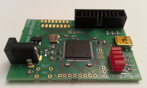
Cortex-M4 mini-evaluation board
05 February 2021Although I had previously made a host board for the ST Microelectronics
STM32L4R5 back in 2018 all I ever got round to doing with it was get together a working linker script with bootstrap code and do some basic GPIO.
At the time it got left behind as I put gave priority to getting up to speed with the NXP LPC11(U)xx and later the Kinetis KE0x Cortex-M0 microcontrollers, and then was overtaken by events.
Aside from working out how to to get RS232 send & receive working, which in practice would mostly be about working out the idiosyncrasies of the UART's BAUD rate generator, there was little else I could have done with it.
Circuit design
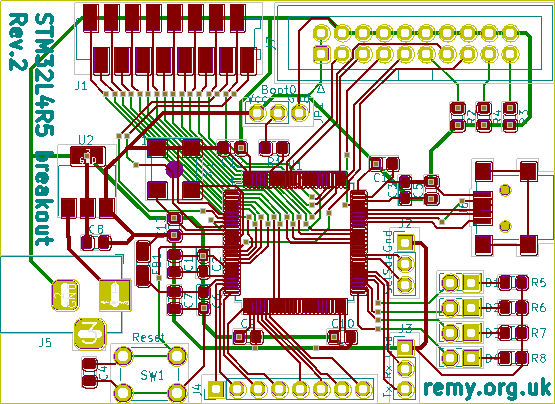
Because the previous host board was designed using KiCad 4 which I have long since stopped using in favour of KiCad 5, this revised board is a complete redesign although some superficial similarities remain. The circuit design follows the power supply recommendations within technical noteAN4555, and fans out dedicated connections for programming, I2C, RS232, and USB.
In trying to keep it general-purpose some pins power on-board indicator LEDs and there are two connectors intended for GPIO — one 8-way 2.54mm pin socket and one 16-way surface-mount MicroMatch connector.
Fabrication & building
Like many of my more recent PCB designs the KiCad files have been open-sourced and are available from my Bitbucket repository. Due to horrendous intercontinental shipping delays I opted to use Aisler rather than JLCPCB as last time I used the latter the boards got stuck in Belgium and due to travel restrictions was unable to receive them. Although I did order in a solder stencil I ended up hand-soldering the circuit boards instead of reflow soldering them — the trick seems to be to liberal with the flux and conservative with the solder.List of components
Most components are from recently-ordered stock but since things got a bit mixed up in relocating all my electronics stuff some of the order codes below might be wrong. Based on my experience with the first-generation breakout board a lot of the capacitors could probably be omitted, and in the case of the ferrite beadFB1 there is no recommended value beyond mentioning that it could be replaced with a short.
One thing to watch out for is tantalum capacitors being polarised — I only realised this when it came to soldering the circuit, and had I known in advance I would have used ceramic capacitors instead.
| Pad | Component | Manufacturer | Part number |
U1 |
ARM Cortex-M4 | ST Microelectronics | STM32L4R5VITx |
U2 |
3.3-volt power regulator | Texas Instruments | UA78M33CDCYR |
X1 |
16MHz Oscillator | Multicomp | MCSJK-6NC2-16.00-25-B |
D1,D2,D3,D4 |
LED | Kingbright |
L-113IDT |
R1,R2,R3,R4 |
10kΩ resistor | Multicomp | MCWR08X1002FTL |
R5,R6,R7,R8 |
1kΩ resistor | Multicomp | MCWR08X1001FTL |
C1,C4,C5,C9 |
0.1μF (100nF) capacitor | Samsung | CL21B104KACNNNC |
C10,C11,C12,C13 |
|||
C2,C3,C6 |
1μF tantalum capacitor | Vishay | TMCP1D105KTRF |
C7 |
0.01μF (10nF) capacitor | Samsung | CL21B103KCANNNC |
C8 |
4.7μF capacitor | Vishay | VJ0805G475KXXTW1BC |
FB1 |
Ferrite bead | TDK | MPZ2012S601AT |
J1 |
16-way MicroMatch socket | TE Connectivity | 1-2178711-6 |
J2,J3,JP1 |
3-way pin header | n/a | |
J4 |
8-way pin header | ||
J5 |
Barrel jack | Cliff Electronic | FC681465P |
J6 |
USB Mini-AB | Multicomp | MC32598 |
J7 |
20-way IDC socket | Multicomp | MC-254-20-00-ST-DIP |
SW1 |
Push button | n/a | |
I have forgotten where I obtained the push button switches but suspect it is from a batch I ordered off E-Bay quite a while back; I am also unsure what order number was used for the pin headers I cut down to size. The price of Cortex-M4 chips has gone up a lot in the last year or two and it alone accounts for the majority of the cost of components.