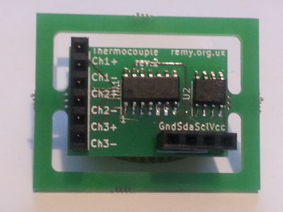
MCP3428 temperature circuit
09 October 2020This circuit is a rework of my previous thermocouple control into a self-contained daughter board that presents an I2C interface. It is part of my longer-term plan for a closed-loop reflow hot-plate controller which I have decided to build using multiple circuit boards that all communicate with the main controller via I2C. I had a lot of trouble with my first thermocouple control circuit so I wanted a minimalist design I could thoroughly test before integrating it into a larger system.
Circuit design
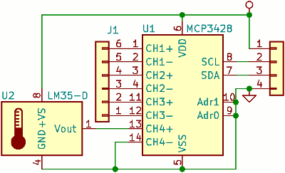
Rather than having a microcontroller as was the case previously, theMCP3428 acts as the external data interface for the circuit, and with both Adr0 and Adr1 tied to ground the MCP3428 has an I2C address of 0xd0. One of the analogue inputs is used for the reference reading from the temperature chip and the other three are for the connection of thermocouples.
A list of components is presented later.
As with most of my recent circuit designs the KiCad files are available. The version I have released is revision 3 although the only difference between than and version 2 pictured in the introduction is changes to silk-screen.
Interface protocol
Although the MicrochipMCP3428 analogue-digital converter chip's data-sheet comes in at 56 pages, the actual I2C control procedure is as simple as they come with all the essential details are on Pages 15 & 18, and these are summarized below.
Controlling the sampling process involves sending a single control byte with the following structure:
| Bit | Function | Values |
| 7 | Trigger (write) |
0: No effect1: Trigger one-shot
|
| Status (read) |
0: Reading is ready1: Sampling in progress
|
|
| 6 | Channel select |
00: Channel 101: Channel 210: Channel 311: Channel 4
|
| 5 | ||
| 4 | Conversion mode |
0: One-shot1: Continious |
| 3 | Sample rate |
00: 240 samples/sec (12 bits)01: 60 samples/sec (14 bits)10: 15 samples/sec (16 bits)11: Unused
|
| 2 | ||
| 1 | Input gain |
00: 1x01: 2x10: 4x11: 8x
|
| 0 |
When doing an I2C read the first two bytes are the sample value and subsequent bytes are the status/control byte with the structure above. Particularly with one-shot sampling the high bit of the third byte should be checked to see whether the voltage value is ready. The size of each unit of reading is summarized in the table below for all combinations of sampling rate and input gain. Note that for a gain of unity all three resolutions can read up to the maximum of 2,048 volts but for higher gains the maximum is proportionally lower.
| Resolution setting | Gain | |||
1x |
2x |
4x |
8x |
|
| 12 bits | 1mV | 500μV | 250μV | 125μV |
| 14 bits | 250μV | 125μV | 62.5μV | 31.25μV |
| 16 bits | 62.5μV | 31.25μV | 15.625μV | 7.8125μV |
Desktop control
Whenever I get a new I2C based device the first thing I normally do is try controlling it from a desktop computer via the Robot Electronics ISS adapter using my Python serial script. Although in the past I made my own I2C master with what I think is an interface that allows easier debugging, it does not have built-in pull-up resistors unlike the former. To use the Robot Electronics adapter the first thing to do is to switch it into hardware 100kHz I2C mode:./ttyTxRx3.py /dev/ttyACM0 1 5a 02 60 05
The adapter documentation suggests using 04 for the last parameter, but I prefer 05 since it puts both the unused ports into input mode rather than tying them high or low.
The following command can then be used to initiate continious sampling and reading at the fastest 12-bit resolution and no gain on channel 4:
./ttyTxRx3.py /dev/ttyACM0 1 53 d0 f0
Channel 4 is the one that the reference temperature chip is wired to. To instead read channel 1 at maximum sensitivity use the following:./ttyTxRx3.py /dev/ttyACM0 1 53 d0 8b
In both cases the follwoing command will read the sampling result:
./ttyTxRx3.py /dev/ttyACM0 3 54 d1 3
Temperature calculations
I had thought about using the same gain and/or sampling rate for both the reference temperature readings and the thermocouples, but since the data-sheet does not mention anything about problems with repeated switching of parameters on a per-sample basis I felt this would just cause complications. I used Python's thermocouples reference module to pre-calculate lookup tables, although for the temperature range I am interested in there are simplifying approximations.Reference temperature conversion
The temperature sensor chip outputs 10mV per degree celsius so for simplicity I opted for the default 12-bit sample rate with no gain, which gives a delta of 1mV and hence 0.1°C. However this needs to be converted into an equivalent thermocouple voltage and for convenience I will use a delta of 7.8125μV as the common currency for the hot junction calculation. This conversion is summarized in the table below for some sample readings:
| Parameter | Example values | |||
| ADC reading | 150 | 200 | 250 | 300 |
| Reference voltage | 150mV | 200mV | 250mV | 300mV |
| Temperature | 15°C | 20°C | 25°C | 30°C |
| Thermocouple voltage | ~0.59697mV | ~0.79811mV | ~1.00025mV | ~1.20327mV |
| 7.8125μV deltas | 76 | 102 | 128 | 154 |
However the microcontrollers I typically use do not have a floating point unit and hence no division operator, so the easiest thing is to simply use a pre-calculated lookup table. As it happens 1,920 is a power-of-two multiple of 15 so there is a lot of scope for using bit-shifts to quantize the size of lookup table for voltage-to-celcius conversions. With final output being rounded to integer values the least two significant bits do not make any difference so the table only needs 480 entries. When I made my previous thermocouple circuitit returned a final temperature as an integer that was actually tenths of a degree and it used a table of just over one thousand entries.
Final temperature lookup
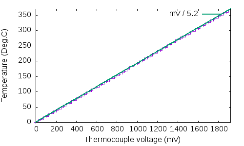
The thermocouples pretty much need something close to maximum sensitivity, so I used the full 16-bit sampling rate together with maximum gain which gives a voltage delta of 7.8125μV. To obtain the absolute temperature of the hot junction the thermocouple voltage is added to the equivalent voltage for the cold junction temperature, and then a lookup is performed on this summed value to get the final temperature. Since the thermocouples have a specified maximum temperature of 350°C I assume a maximum voltage of 15mV which corresponds to 366°C, which with a 7.8125μV voltage deltas means a maximum digital value of 1,920. Over this range the conversion can be approximated by division by 5.2:
However implementing this on a chip that does not have a floating point unit may actually be more effort than doing a lookup, although this brings in trade-off related to available storage space.
1,920 is a power-of-two multiple of 15 so there is a lot of scope for using bit-shifts to quantize the size of lookup table for voltage-to-celcius conversions, if the 4 kilobytes needed to store all 1,920 values is too much.
When I made my previous thermocouple circuit I was using a Microchip PIC12F1840 where I had to reduce the table size a lot, but on the ARM Cortex-M0 based chips this is not going to be an issue.
List of components
The table below give the manufacturer and part number details for the various components used for this circuit. Compared to most other components I use, the MicrochipMCP3428 is a relatively expensive chip at €3 each but the analogue-digital conversion built into microcontrollers is not sensitive enough for the micro-volt readings required for thermocouples.
Thermocouples themselves are around €6 each.
| Component | Manufacturer | Part number |
| Thermocouple | Labfacility | Z3-K-1M |
| Analog-digital converter | Microchip | MCP3428 |
| Temperature sensor chip | Texas Instuments | LM35DM/NOPB |
Remarks
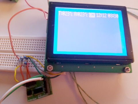
I got the labels for the thermocouples connections flipped which caused some wild goose chases but aside from this the circuit was essentially a success — given the difficulties I had with the original board that included a microcontroller I had expected more trouble, but this was partly due to the circumstances of the time I made the latter. At time of writing I have hooked the daughter-board to my dot-matrix LCD display and got it to display the hot & cold junction temperaturs.
With this temperature board done and AC power control in progress I am hoping to be able to do closed-loop testing around new-year, and a major purpose of this article is to remind me when the time comes how this part works.